System and method for writing to a magnetic shift register

a technology of magnetic shift register and writing system, applied in the field of memory storage system, can solve the problems of solid-state random access memory, inability to inability to reliably write to the magnetic shift register, etc., and achieve the effect of high cost of mechanical means, high reading cost, and variable capacity of the magnetic shift register

Inactive Publication Date: 2005-05-24
GLOBALFOUNDRIES US INC
View PDF21 Cites 129 Cited by
  • Summary
  • Abstract
  • Description
  • Claims
  • Application Information

AI Technical Summary

Benefits of technology

[0026]The capacity of the magnetic shift register can be varied over a wide range continuously by simply varying the number of magnetic shift register tracks per memory device. This is a particular advantage over magnetic hard disk drives in which because of the high cost of the reading and writing heads and their circuitry, and the high cost of the mechanical means of moving these heads and the magnetic media, a hard disk drive only provides a cheap means of storage when many gigabytes of data are stored, such that the cost of the mechanical components of the hard disk driv

Problems solved by technology

However, disk drives are inherently unreliable.
Devices with moving parts tend to wear out and fail.
Solid state random access memories currently store data on the order of 1 GB (gigabyte) per device, and are relatively expensive, per storage unit, i.e., per 1 GB, compared to a disk drive.
In addition, flash memory cells could begin to lose data after less than a million write cycles.
While this may be adequate for some applications, flash memory cells would begin to fail rapidly if used constantly to write new data, such as in a computer's main memory.
Further, the access time for flash memory is much too long for computer applications.
However, commercially available memory capacities are currently low, on the order of

Method used


Image

  • System and method for writing to a magnetic shift register
  • System and method for writing to a magnetic shift register
  • System and method for writing to a magnetic shift register

Examples


Embodiment Construction

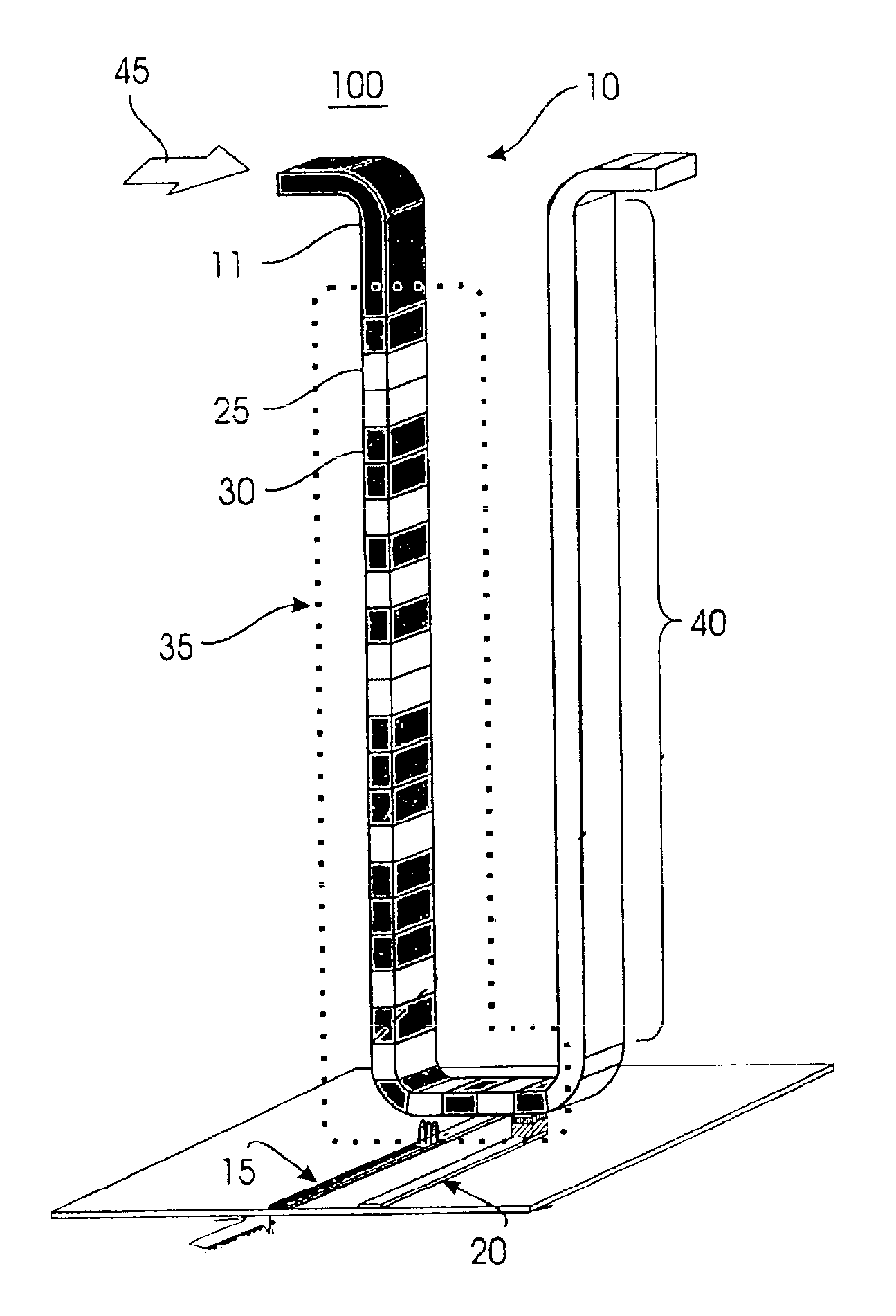
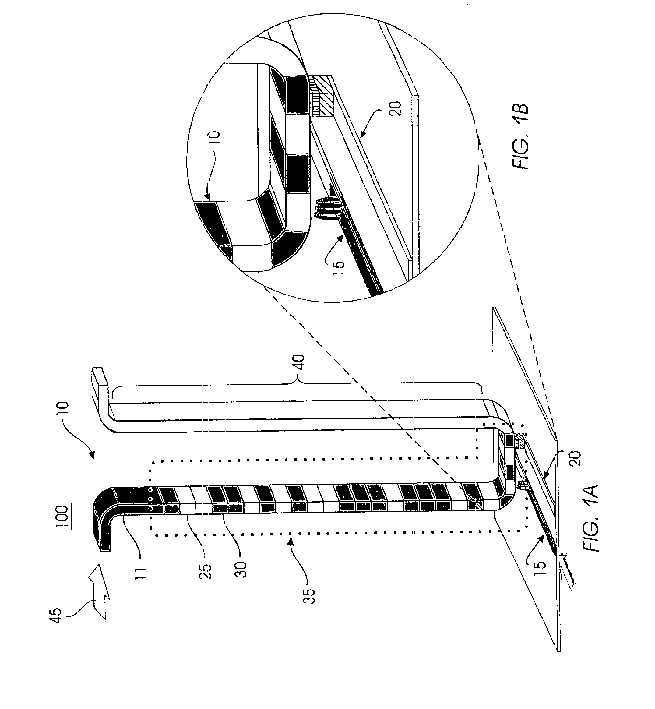
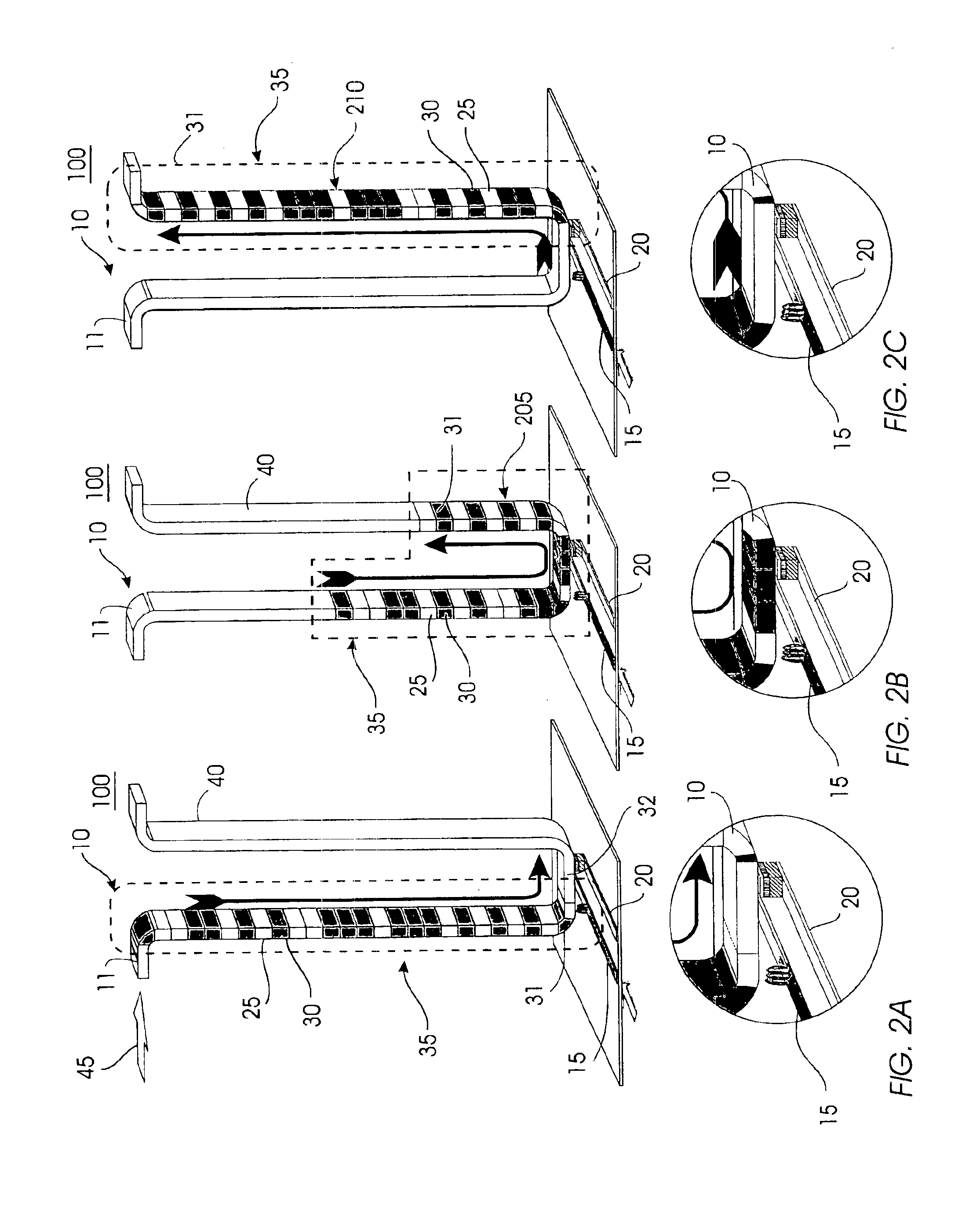
[0050]FIG. 1 (FIGS. 1A and 1B) illustrates an exemplary high-level architecture of a magnetic memory system 100 comprising a magnetic shift register 10 that utilizes a writing device (also referred to herein as writing element) 15 and a reading device (also referred to herein as reading element) 20. Both the reading device 20 and the writing device 15 form a read / write element of system 100.

[0051]The magnetic shift register 10 comprises a fine track 11 made of ferromagnetic material. The track 11 can be magnetized in small sections, or domains, in one direction or another. Information is stored in regions such as domains 25, 30 in the track 11. The order parameter of the magnetic material from which the track is fabricated, that is the magnetization direction or the direction of the magnetic moment, changes from one direction to another. This variation in the direction of the magnetic moment forms the basis for storing information in the track 11.

[0052]In one embodiment, the magneti...


PUM


Abstract

A writing device can change the direction of the magnetic moment in a magnetic shift register, thus writing information to the domains or bits in the magnetic shift register. Associated with each domain wall are large magnetic fringing fields. The domain wall concentrates the change in magnetism from one direction to another in a very small space. Depending on the nature of the domain wall, very large dipolar fringing fields can emanate from the domain wall. This characteristic of magnetic domains is used to write to the magnetic shift register. When the domain wall is moved close to another magnetic material, the large fields of the domain wall change the direction of the magnetic moment in the magnetic material, effectively “writing” to the magnetic material.

Description

CROSS-REFERENCE TO RELATED APPLICATION[0001]The present application is related to co-pending U.S. patent application titled “Shiftable Magnetic Shift Register and Method of Using the Same,” which was filed on even date herewith, which is assigned to the same assignee as the present application, and which is incorporated herein by reference.FIELD OF THE INVENTION[0002]The present invention generally relates to memory storage systems, and particularly to a memory storage system that uses the magnetic moment of magnetic domains to store data. Specifically, the present invention relates to a system that uses fringing fields associated with domain walls for writing to such a memory storage system.BACKGROUND OF THE INVENTION[0003]The two conventional common non-volatile data storage devices are: disk drives and solid state random access memories (RAM). Disk drives are capable of inexpensively storing large amounts of data, i.e., greater than 100 GB. However, disk drives are inherently unr...

Claims


Application Information

Patent Timeline
IPC IPC(8): G11C11/14G11C11/02H01F41/26H01F10/12H01F41/14H01F10/14G11C19/08
CPCG11C11/14G11C19/0808G11C19/0841H01F41/26H01F10/14
Inventor PARKIN, STUART S. P.
Owner GLOBALFOUNDRIES US INC
Why Eureka
Try Eureka