De-icing or defogging system for optical instrument and image acquisition device provided with said system

A technology for image acquisition devices and optical instruments, which is applied in the field of defrosting or defogging systems, image acquisition devices, and cameras, and can solve problems such as device failure and high cost of observation windows

Inactive Publication Date: 2010-06-30
AIRBUS OPERATIONS (SAS)
View PDF1 Cites 33 Cited by
  • Summary
  • Abstract
  • Description
  • Claims
  • Application Information

AI Technical Summary

Problems solved by technology

However, the cost of these observation windows is too high, and when maintaining the acquisition device, these wires may be cut due to carelessness during disassembly, thereby rendering the device useless

Method used


Image

  • De-icing or defogging system for optical instrument and image acquisition device provided with said system
  • De-icing or defogging system for optical instrument and image acquisition device provided with said system
  • De-icing or defogging system for optical instrument and image acquisition device provided with said system

Examples


Embodiment Construction

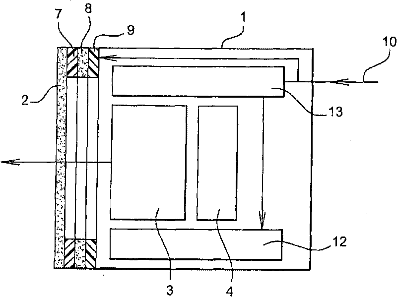
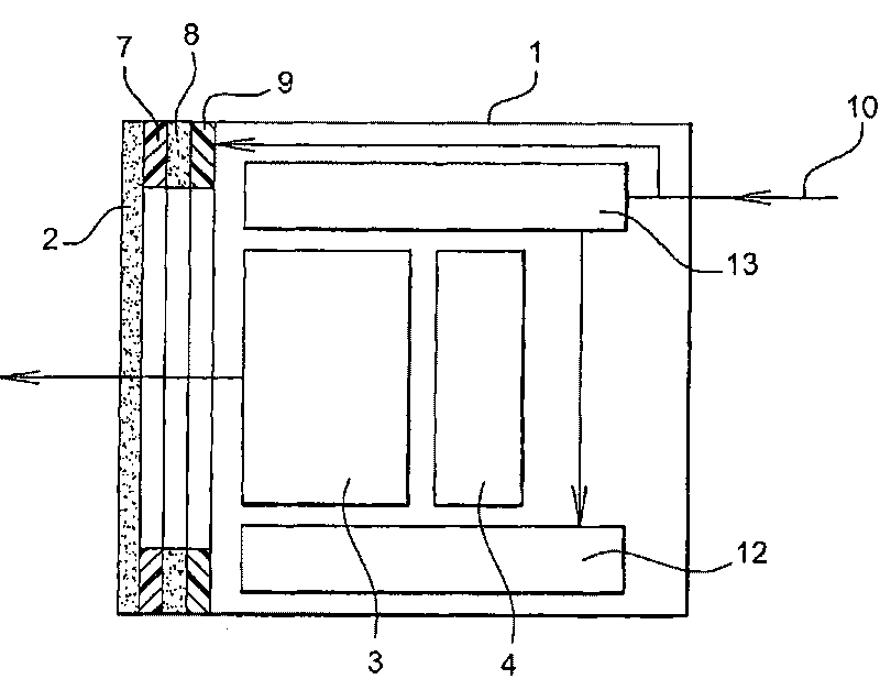
[0049] figure 1 An image acquisition device according to a preferred embodiment of the present invention is shown.

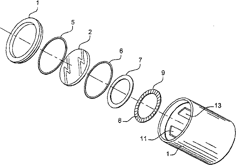
[0050] The device comprises a protective housing 1 on which a viewing window 2 is mounted. In the housing 1, along the traveling direction of light from the outside toward the sensor, a lens 3 and a sensor 4, such as a CCD sensor with a light detection dot matrix, are placed.

[0051] Lens 3 may be a zoom lens for magnifying an object fixed relative to the device.

[0052] The housing also houses a control circuit (not shown) for the sensor and its lens.

[0053] The tightness of the device is ensured by gaskets 5 , 6 interposed between the viewing window 2 and the casing of the protective housing 1 .

[0054] The device also has a defrosting or defogging system of the viewing window 2 covered on its inner surface by a thermally conductive film 7 placed on the edge of the active area of ​​the viewing window. Here, the membrane 7 has an annular shape.

[005...


PUM


Abstract

The invention relates to a defogging or de-icing system for an optical instrument including a protection housing (1). According to the invention, the system includes: a porthole (2) covered on at least one face thereof with a heat conducting film (7) provided at the edge of the useful area of said porthole (2), the porthole being mounted on the protection housing (1), heating members (8) placed in contact with the film for heating said film, and a power supply circuit (9, 10) for the heating members (8).

Description

technical field [0001] The invention relates to a defrosting or defogging system of an optical instrument, such as an image acquisition device. It also relates to an image acquisition device equipped with such a defrosting and / or defogging device. [0002] The invention is particularly suitable for cameras equipped on aircraft. Background technique [0003] It is known to equip external cameras at fixed locations on board the aircraft to monitor a defined area of ​​the aircraft and / or its surroundings. These cameras allow pilots to observe important parts of the aircraft in real time or parts that cannot be reached, such as wings, landing gear, cargo bay and so on. [0004] As a typical example, such cameras enable precise observation of the position of the wheels on the runway and possible obstacles while the aircraft is taxiing on the ground. [0005] However, these cameras are subjected to the extreme external conditions of the altitude at which the aircraft is flown. ...

Claims


Application Information

Patent Timeline
Patent Type & Authority Applications(China)
IPC IPC(8): H05B3/84B64D47/08B64D15/12
CPCH05B3/84
Inventor L·迪谢纳P·布拉穆莱
Owner AIRBUS OPERATIONS (SAS)
Why Eureka
Try Eureka