Automatic bending machine for inflating valve

A valve and automatic technology, applied in the direction of feeding device, positioning device, storage device, etc., can solve the problems of unstable processing quality, unsafety, large pin shaft force, etc., and achieve stable and reliable product quality and high degree of automation , the effect of high production efficiency

Inactive Publication Date: 2010-07-07
厦门厦晖橡胶金属工业有限公司
View PDF0 Cites 14 Cited by
  • Summary
  • Abstract
  • Description
  • Claims
  • Application Information

AI Technical Summary

Problems solved by technology

[0002] The commonly used valve bending process is to use a simple device to hold the valve to perform the bending operation, which is inefficient and unsafe
Moreover, its positioning mainly depends on a small pin shaft, which bears a large force, is easy to deform, and has unstable processing quality.
This customary processing method is inconvenient, time-consuming and inconvenient to replace the mold during the conversion process of each process.

Method used


Image

  • Automatic bending machine for inflating valve
  • Automatic bending machine for inflating valve
  • Automatic bending machine for inflating valve

Examples


Embodiment Construction

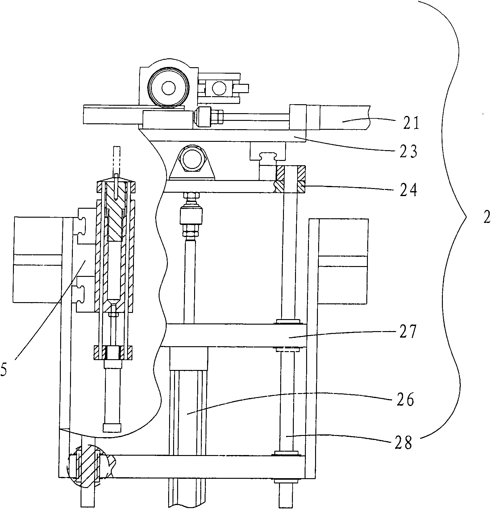
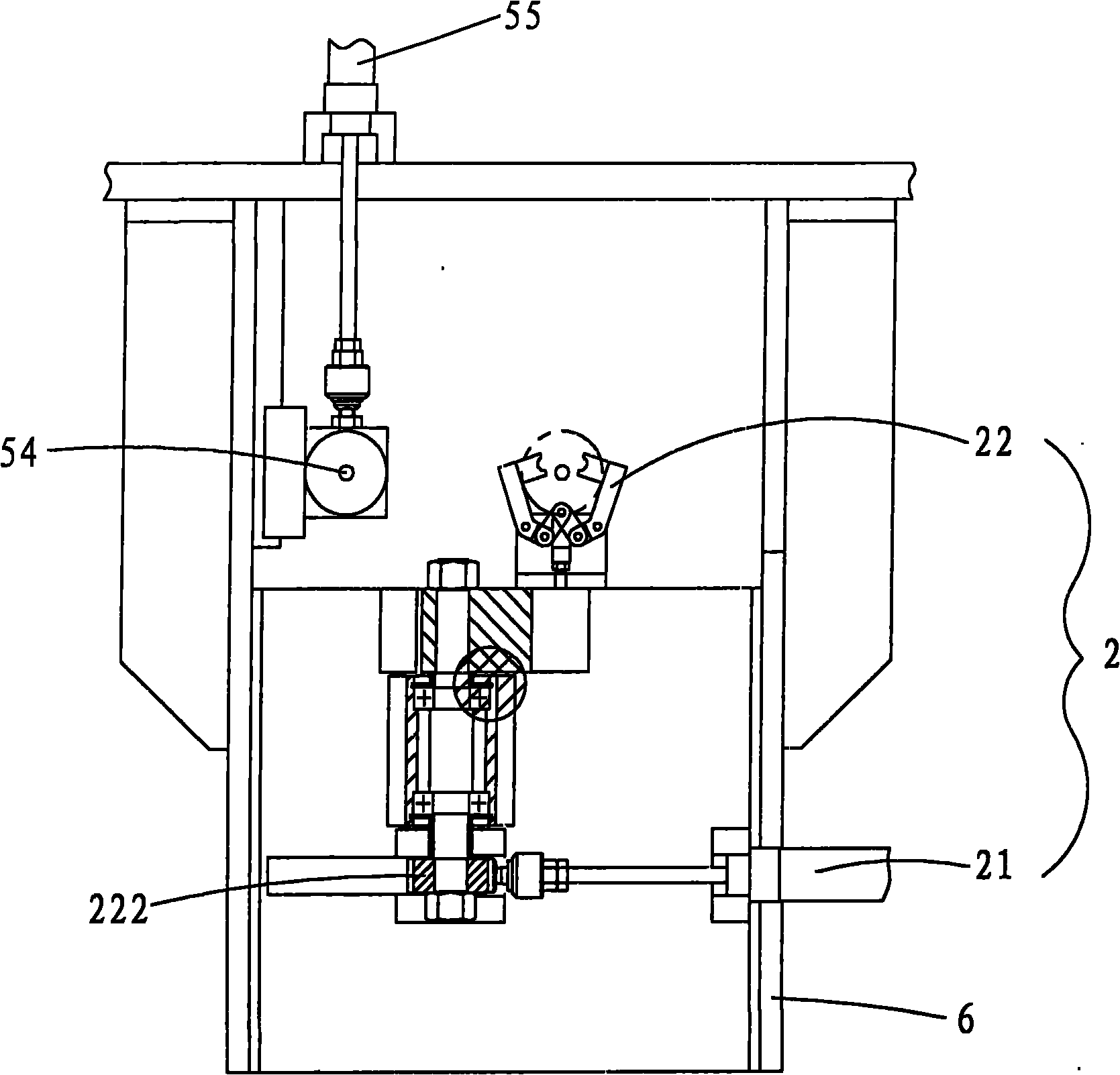
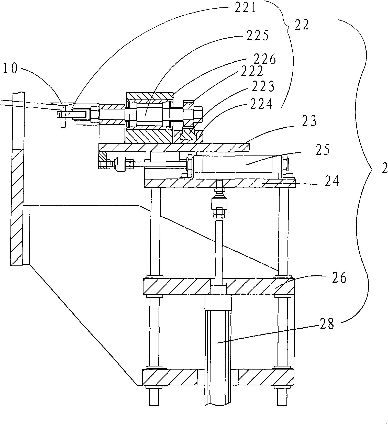
[0021] Such as figure 1 refer to figure 2 , image 3 As shown, the present invention is an automatic valve bending machine, which is mainly composed of a feeding tray 1, a feeding mechanism 2, a clamping and positioning mechanism 3, a bending mechanism 4, a material returning mechanism 5 and a frame 6.

[0022] The feeding mechanism 2 is installed on the frame 6 and the pneumatic finger 221 on it is located below the feeding tray 1; the clamping positioning mechanism 3 is installed on the frame 6 and the clamps 33 on it are aligned The feeding block 54 of the material return mechanism is so as to clamp the workpiece; the described material return mechanism 5 is installed on the frame 6 and the feeding block 54 on it is located at the end point of the running track line of the pneumatic finger 221 of the feeding mechanism 2, so as to accommodate Valve 10.

[0023] Described feeding mechanism 2 comprises clamping cylinder 21, clamping mechanism 22, front and rear sliding pla...


PUM


Abstract

The invention discloses an automatic bending machine for an inflating valve, which mainly comprises a feed tray, a feed mechanism, a clamping and positioning mechanism, a bending mechanism and a material returning mechanism. The feed mechanism is arranged on a frame and a pneumatic finger on the feed mechanism is positioned under the feed tray. The clamping and positioning mechanism is arranged on the frame and a clamp opening on the clamping and positioning mechanism is aligned with a workpiece positioning surface of the material returning mechanism so as to clamp a workpiece. The material returning mechanism is arranged on the frame and a feed block on the material returning mechanism is positioned at the terminal point of a motion track line of the pneumatic finger of the feed mechanism. Because the steps of feeding, clamping and positioning, bending and returning the material are finished at one time, the automatic bending machine for the inflating valve has the advantages of high degree of automation, stable and reliable quality of the produced product, and high production efficiency. In addition, when the workpiece is clamped by the clamping and positioning mechanism, the workpiece is clamped with stressed dead points, so that the clamping and stressing are reliable. The mold is quickly exchanged, and is conveniently regulated.

Description

technical field [0001] The invention relates to a valve processing equipment, in particular to an automatic valve bending machine. Background technique [0002] The usual valve bending process is to use a simple device to hold the valve to perform the bending operation, which is inefficient and unsafe. And its location mainly depends on a small pin shaft positioning, and the pin shaft is stressed, easily deformed, and the processing quality is unstable. This conventional processing method is inconvenient, time-consuming and inconvenient to change the mold during the conversion process of each process. Contents of the invention [0003] The object of the present invention is to provide an automatic valve bending machine with high product quality and high degree of automation. [0004] For realizing the above object, technical solution of the present invention is: [0005] The invention is an automatic valve bending machine, which is mainly composed of a feeding tray, a f...

Claims


Application Information

Patent Timeline
Patent Type & Authority Applications(China)
IPC IPC(8): B21D7/024B21D7/16B21D43/10B21D43/00B21D45/00
Inventor 曾创造江峰川
Owner 厦门厦晖橡胶金属工业有限公司
Why Eureka
Try Eureka