Feeding and discharge switch valve for food filling

A switching valve and filling technology, which is applied in the field of switching valves, can solve problems such as accelerated material aging, inability to achieve high-level CIP cleaning, and increased equipment operating costs.

Active Publication Date: 2010-07-07
HANGZHOU ZHONGYA MACHINERY CO LTD
View PDF5 Cites 21 Cited by
  • Summary
  • Abstract
  • Description
  • Claims
  • Application Information

AI Technical Summary

Problems solved by technology

[0002] In the food volumetric quantitative filling system, the valve body and the rotary valve core in the switching rotary valve for feeding and discharging materials have metal-metal, metal-plastic, metal-ceramic and other material combinations, because the valve body and the rotary valve core It needs to be rotated to realize the switch between feeding and discharging, and it needs to be able to rotate after being heated and expanded at high temperature during automatic cleaning in place (CIP). The radial gap must be enlarged and sealed with sealing elements; Due to the existence of gaps, the structure has the disadvantage of being difficult to clean the dead corners. At the same time, due to the continuous changes in the environment of alternating cold and heat, the sealing element will accelerate the aging speed of the material and shorten the service life, resulting in an increase in the operating cost of the equipment.
In addition, due to the sealing of the sealing element, it is difficult to achieve a large distance of axial sliding and cannot achieve high-position CIP cleaning

Method used


Image

  • Feeding and discharge switch valve for food filling
  • Feeding and discharge switch valve for food filling
  • Feeding and discharge switch valve for food filling

Examples


Embodiment Construction

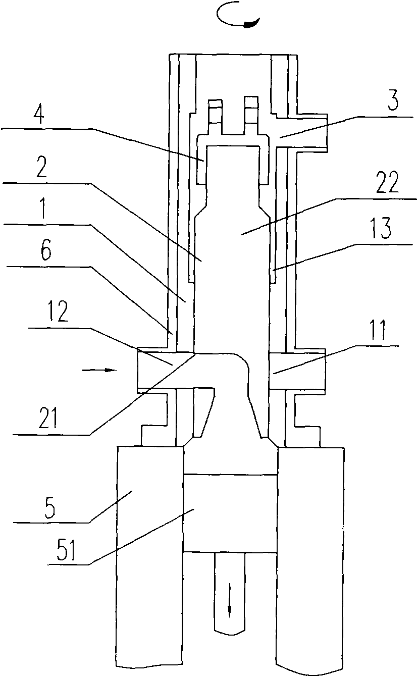
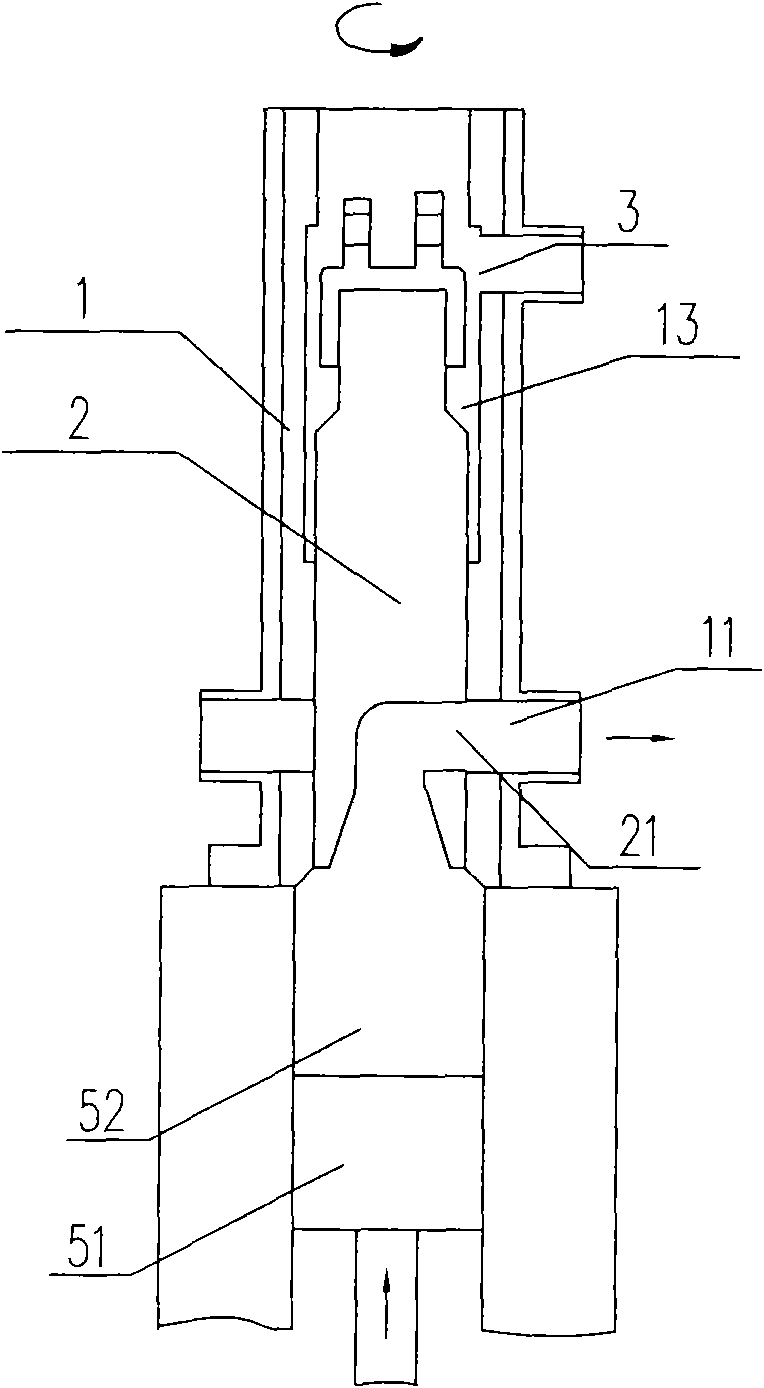
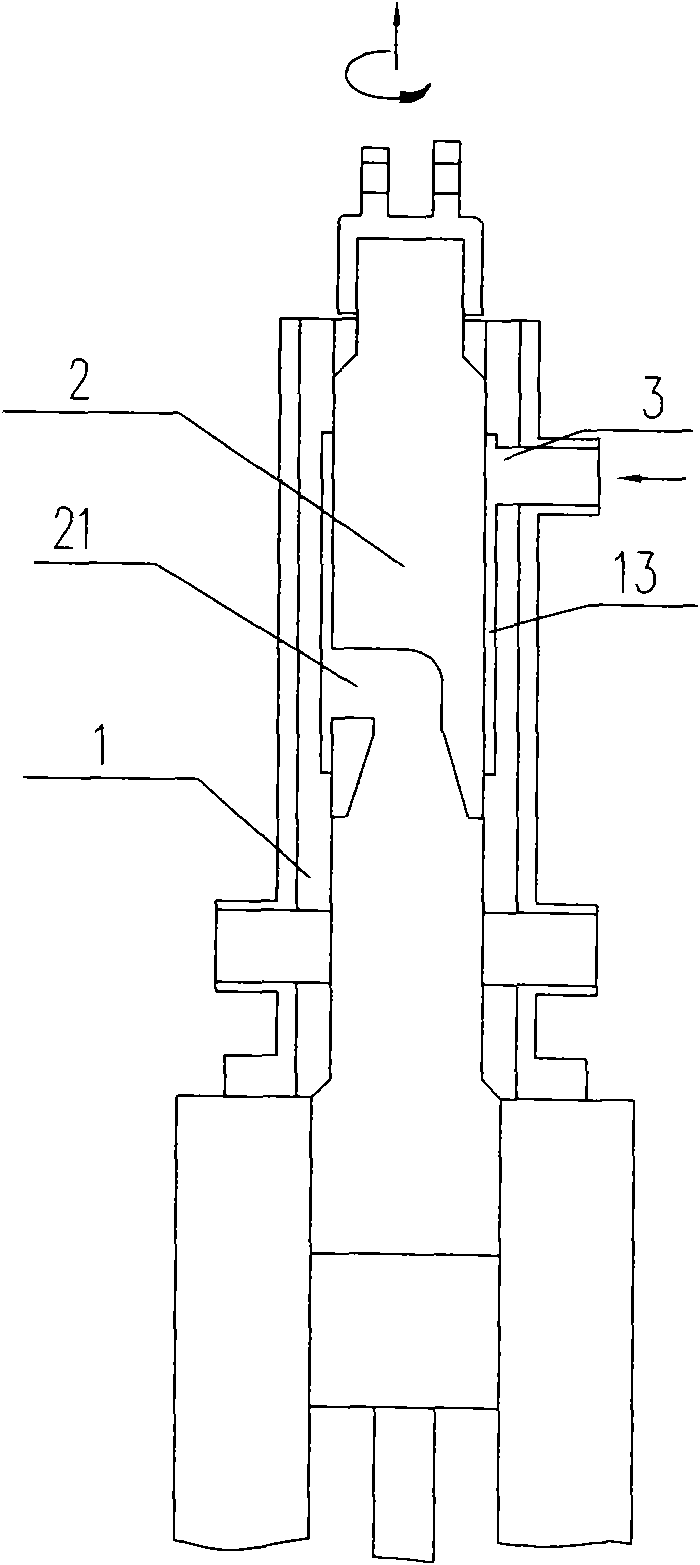
[0007] Refer to attached picture. The present invention comprises a valve body 1 and a valve core 2, on which a discharge port 11 and a feed port 12 are arranged, the valve core has a switching connection port 21 for the discharge port and the feed port, the valve body Ceramic materials are used to seal and cooperate with the valve core around the discharge port and the feed port to form a partition for the material in the valve body.

[0008] Both the valve core 2 and the valve body 1 are made of ceramics, or only around the discharge port and the feed port and the valve core are sealed with ceramic materials.

[0009] The spool 2 is a rotatable and axially slidable spool, and the valve body 1 is provided with a fully automatic cleaning-in-place (CIP) cleaning port 3 above the discharge port 11 and the feed port 12 and cleaning Cavity 13, so as to realize high-position CIP cleaning of the valve core.

[0010] The upper end of the valve core 2 is fastened with a connecting p...


PUM


Abstract

The invention provides a feeding and discharging switch valve for food filling, which comprises a valve body and a valve core; a discharging port and a feeding port are arranged on the valve body, the valve core is provided with a switch joint port for the discharging port and the feeding port, and the valve body adopts ceramic material on the periphery of the discharging port and the feeding port, and the valve core to realize seal fit and form isolation of material. As the technical scheme of the invention is adopted, the sealing of valve core and the valve body is guaranteed only through size accuracy, no additional seal element is needed, the material isolation is realized and the sealing is realized, as the abrasion resistance of the ceramic is higher, the service life of the switch valve is longer due to smaller abrasion; as the ceramic material has stability, the thermal deformation coefficient is very small, the condition that the valve body and the valve core cannot rotate and axially slide due to thermal expansion interference after being heated is not happened so the high position CIP cleaning can be realized conveniently.

Description

technical field [0001] The invention relates to a switching valve for volumetric food filling and discharging. Background technique [0002] In the food volumetric quantitative filling system, the valve body and the rotary valve core in the switching rotary valve for feeding and discharging materials have metal-metal, metal-plastic, metal-ceramic and other material combinations, because the valve body and the rotary valve core It needs to be rotated to realize the switch between feeding and discharging, and it needs to be able to rotate after being heated and expanded at high temperature during automatic cleaning in place (CIP). The radial gap must be enlarged and sealed with sealing elements; Due to the existence of gaps, the structure has the disadvantage of being difficult to clean in the sanitary dead corners. At the same time, the sealing element is subjected to constant changes in the environment of alternating cold and heat, which makes the material aging faster and h...

Claims


Application Information

Patent Timeline
Patent Type & Authority Applications(China)
IPC IPC(8): B67C3/22F16K27/00F16K41/02F16K41/00
Inventor 史正吉永林孙志芳周强华
Owner HANGZHOU ZHONGYA MACHINERY CO LTD
Why Eureka
Try Eureka