
Wall-mounted electromagnetic damping motion demonstrating board

A technology of electromagnetic damping and demonstration board, which is applied in the direction of educational appliances, instruments, teaching models, etc., to achieve the effect of improving visibility and occupying a small space

Inactive Publication Date: 2010-07-07
上海市嘉定区第二中学
View PDF0 Cites 0 Cited by
  • Summary
  • Abstract
  • Description
  • Claims
  • Application Information

AI Technical Summary

Problems solved by technology

However, the orbits of the magnets in the existing experimental devices are all copper or aluminum tubes, leading some teachers and students to think that "the orbit must be closed to produce electromagnetic induction".

Method used


Image

  • Wall-mounted electromagnetic damping motion demonstrating board
  • Wall-mounted electromagnetic damping motion demonstrating board

Examples


Embodiment

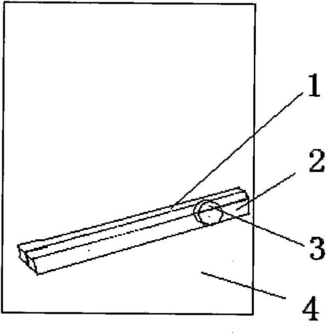
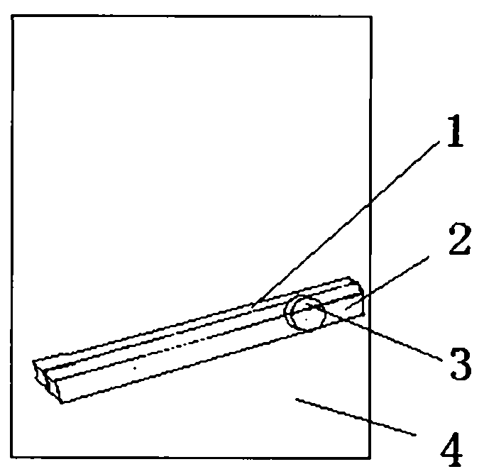
[0018] 1) A wall-mounted electromagnetic damping motion demonstration board as shown in the figure, which is composed of a plastic groove track, an aluminum groove track, a cylindrical magnet, and a vertical plate.

[0019] 2) The plastic groove track is fixed on the vertical plate.

[0020] 3) The aluminum groove track is fixed on the plastic groove track.

[0021] 4) The cylindrical magnet is placed in the groove of the track.

[0022] 5) The size of the vertical plate: 300mm×400mm.

[0023] 6) The dimensions of the plastic groove track and aluminum groove track: length 300mm, depth 30mm, width 22mm.

[0024] 7) Dimensions of the cylindrical magnet: height 20mm, diameter 40mm.


PUM


Abstract

The invention discloses a wall-hanging electromagnetic damping motion demonstrating board. The device comprises a plastic groove rail, an aluminum groove rail, a cylinder magnet and a vertical plate, wherein the plastic groove rail is fixed on the vertical plate; the aluminum groove rail is fixed on the plastic groove rail; and the cylinder magnet is placed in a groove of the rail. The wall-mounted electromagnetic damping motion demonstrating board has the advantages of simple operation, obvious phenomena and the like, and is suitable to be used as an exhibit in a student break experiment or a science and technology museum in a school.

Description

Technical field: [0001] The invention relates to a demonstration teaching aid for physics teaching, in particular to a wall-mounted electromagnetic damping motion demonstration board. Background technique: [0002] In high school physics teaching, "Electromagnetic Induction Phenomenon and Its Law" is the teaching focus and also the teaching difficulty. The best way to break through this difficulty is to let students do some experiments on "electromagnetic induction phenomenon" by themselves. The experiment of "electromagnetic damping motion" is one of the experiments that students are most interested in. However, the orbits of the magnets in the existing experimental devices are all copper or aluminum tubes, leading some teachers and students to think that "the orbit must be closed to produce electromagnetic induction". Invention content: [0003] Aiming at the deficiencies in the prior art, the purpose of the present invention is to provide an interactive wall-mounted el...

Claims


Application Information

Patent Timeline
IPC IPC(8): G09B23/18
Inventor 蔡文学姚成兴董洁婷王绳
Owner 上海市嘉定区第二中学
Learn More