
Three-phase voltage type PWM converter capable of reducing output common-mode voltage and modulation method thereof

A technology of three-phase voltage and common-mode voltage, which is applied in the direction of converting irreversible DC power input into AC power output, can solve the problems of poor quality of output differential-mode voltage, poor output current waveform, and increased cost, etc. The effect of low, weakening harm, and simple hardware circuit structure

Inactive Publication Date: 2012-07-25
CHINA UNIV OF PETROLEUM (EAST CHINA)
View PDF0 Cites 0 Cited by
  • Summary
  • Abstract
  • Description
  • Claims
  • Application Information

AI Technical Summary

Problems solved by technology

Its disadvantages: ①Increase the cost, not only the switching device of a bridge arm, but also the filter element, the cost is high; ②Because the zero vector is not used, the quality of the output differential mode voltage is deteriorated, and the output current waveform is also poor

Method used


Image

  • Three-phase voltage type PWM converter capable of reducing output common-mode voltage and modulation method thereof
  • Three-phase voltage type PWM converter capable of reducing output common-mode voltage and modulation method thereof
  • Three-phase voltage type PWM converter capable of reducing output common-mode voltage and modulation method thereof

Examples


Embodiment Construction

[0023] In conjunction with accompanying drawing, the present invention is further described:

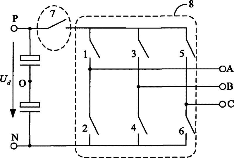
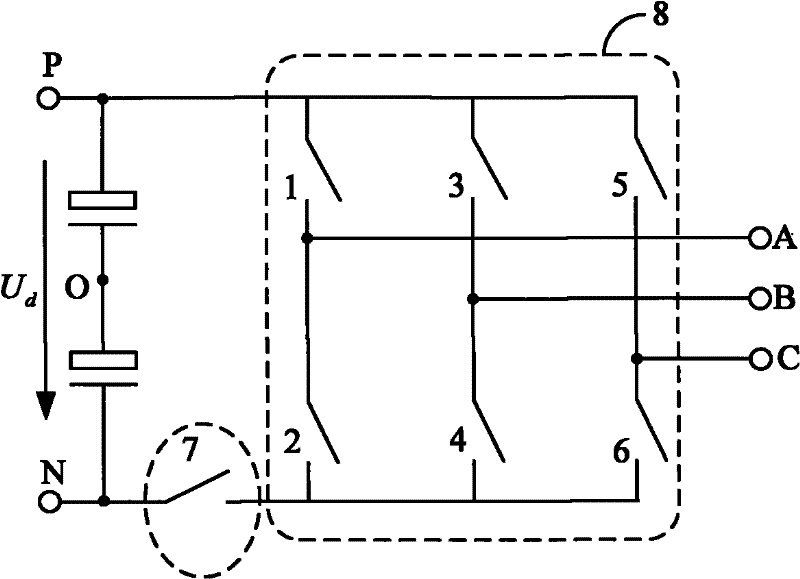
[0024] 1. The hardware circuit structure consists of fully controlled power electronic devices such as IGBTs and MOSFETs and diodes to form a bidirectional switch, or directly adopts a commercialized bidirectional semiconductor power switch. According to Fig. 1 (a) or Fig. 1 (b) Shown to form two kinds of circuit structures. Add a bidirectional fully controlled switch (7) between the positive DC bus (P) or negative DC bus (N) and the traditional PWM converter (8), the bidirectional fully controlled switch is composed of IGBT, MOSFET or other power electronic devices Combination, or directly a bidirectional fully controlled power electronic device. When the PWM converter outputs a voltage space vector, the common-mode voltage output by the PWM converter can be reduced by properly controlling the on and off of the bidirectional full-control switch 7 . The turn-on and turn-off of the ...


PUM


Abstract

The invention relates to a three-phase voltage type PWM converter capable of reducing output common-mode voltage and a modulation method thereof. A circuit has two types and has a circuit structure that a bidirectional fully-controlled switch is additionally arranged between a positive or negative DC bus N and a traditional PWM converter. In the modulation method, as to the circuit shown in Figure 1(a), the PWM converter completely adopts (111) when outputting a zero vector, and the bidirectional fully-controlled switch is turned off when the PWM converter outputs the zero vector and is turned on when the PWM converter outputs an effective vector; as to the circuit shown in Figure 1(b), the converter completely adopts (000) when outputting the zero vector, and the bidirectional fully-controlled switch is turned off when the converter outputs the zero vector and is turned on when the converter outputs the effective vector. The three-phase voltage type PWM converter not only can be usedin a grid-connected power generating system of such renewable energy sources as three-phase solar energy, wind power, fuel battery and the like, but also can be used in a three-phase frequency changer system for lessening damage caused by the common-mode voltage.

Description

1. Technical field: [0001] The invention relates to a three-phase voltage-type PWM converter capable of reducing the output common-mode voltage and a modulation method thereof. 2. Background technology: [0002] Three-phase voltage-type PWM converters are widely used in grid-connected power generation systems of renewable energy such as solar energy, wind energy, and fuel cells, and in control systems of three-phase AC motors. However, the traditional three-phase voltage-type PWM converter also brings many negative effects, one of which is the output of high-frequency common-mode voltage. It will induce a high-amplitude shaft voltage on the motor shaft and form a bearing current, which will damage the motor bearing in a short time and shorten the service life of the motor; or cause grid-connected leakage current, affecting the reliability of the renewable energy grid-connected power generation system run. [0003] The existing methods for suppressing the output common-mode...

Claims


Application Information

Patent Timeline
Patent Type & Authority Patents(China)
IPC IPC(8): H02M7/48
Inventor 赵仁德王永军刘星马帅许强
Owner CHINA UNIV OF PETROLEUM (EAST CHINA)
Learn More