Power amplification circuit and thermally induced sound-producing device with power amplification circuit

A power amplifier circuit and thermal sound generation technology, applied in power amplifiers, amplifiers, transducer circuits, etc., can solve the problems of low sound generation efficiency and large sound generation power consumption of the thermal sound generation element 120, and achieve low power consumption and sound generation high efficiency effect

Active Publication Date: 2010-07-07
BEIJING FUNATE INNOVATION TECH
View PDF0 Cites 16 Cited by
  • Summary
  • Abstract
  • Description
  • Claims
  • Application Information

AI Technical Summary

Problems solved by technology

However, this kind of power amplification method makes the thermoacoustic element 120

Method used


Image

  • Power amplification circuit and thermally induced sound-producing device with power amplification circuit
  • Power amplification circuit and thermally induced sound-producing device with power amplification circuit
  • Power amplification circuit and thermally induced sound-producing device with power amplification circuit

Examples


Embodiment Construction

[0025] The power amplifying circuit of the embodiment of the present invention and the thermoacoustic device using the power amplifying circuit will be described in detail below with reference to the accompanying drawings.

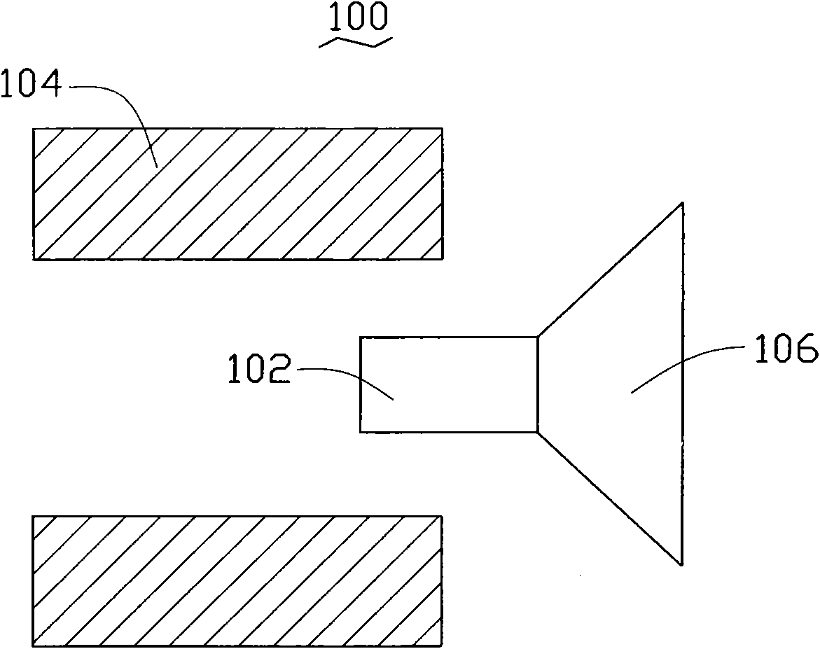
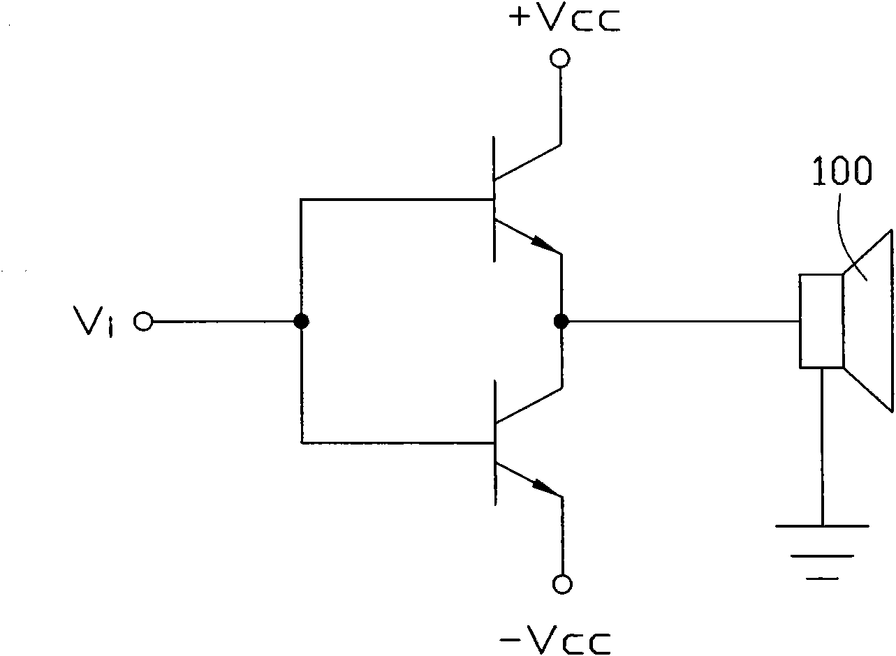
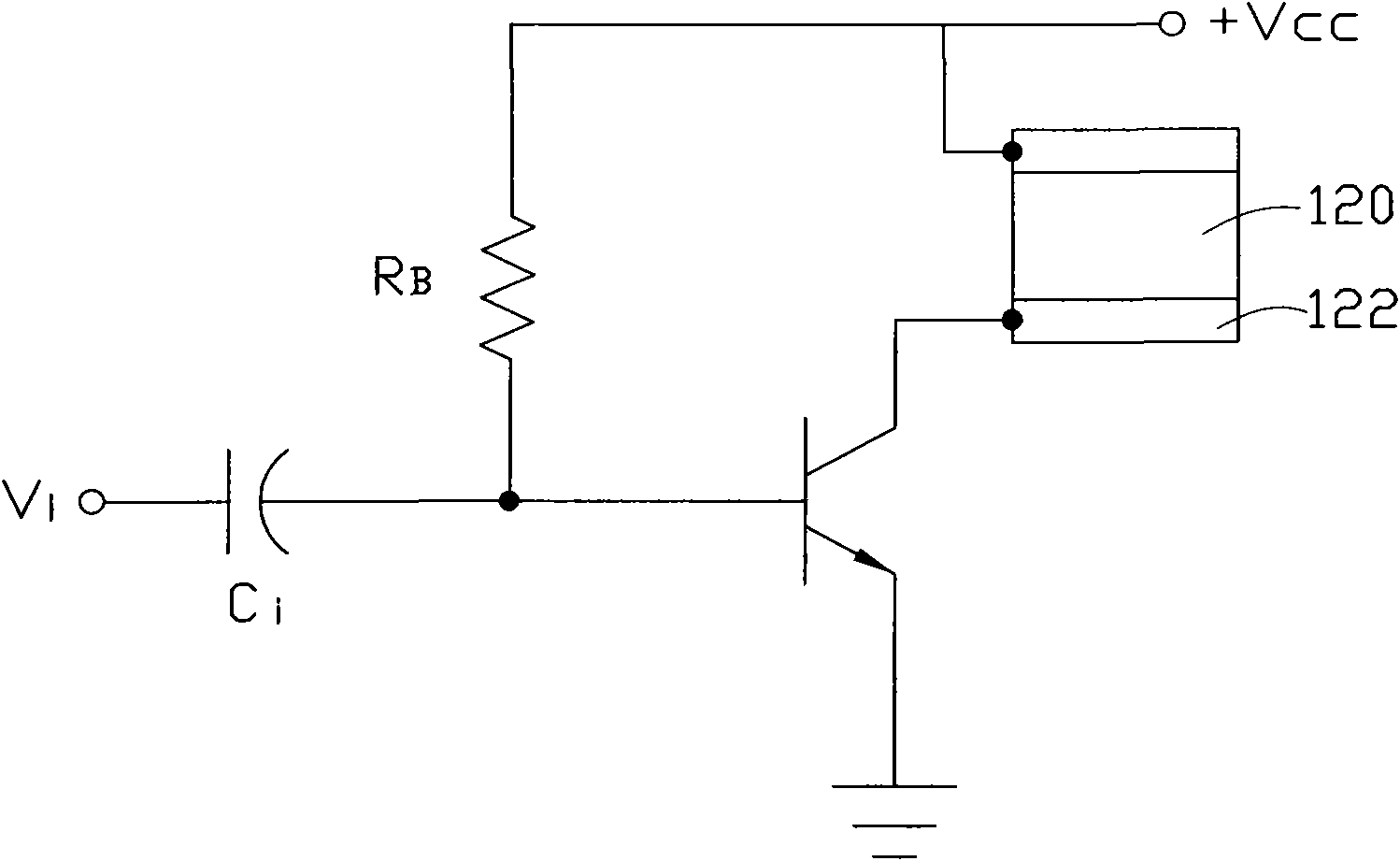
[0026] see Figure 4 , the embodiment of the present invention provides a power amplifier circuit 200 . The power amplifying circuit 200 has an input terminal 202 and an output terminal 204 . The input terminal 202 of the power amplifying circuit 200 is used to receive an audio electrical signal, and the power amplifying circuit 200 outputs an amplified voltage signal to a thermoacoustic element 300 through its output terminal 204 after processing the audio electrical signal to drive the thermoacoustic element 300. The sound emitting element 300 emits sound. In this embodiment, the electrical audio signal is an analog signal.

[0027] The power amplifier circuit 200 includes a peak hold circuit 210 , an addition and subtraction circuit 220 and a power a...


PUM


Abstract

The invention relates to a power amplification circuit for a thermally induced sound-producing device, which comprises a peak holding circuit, an addition and subtraction circuit and a power amplifier. The peak holding circuit is used for receiving an audio electrical signal and outputting a peak holding signal; the addition and subtraction circuit is used for receiving the audio electrical signal and the peak holding signal, comparing the audio electrical signal and the peak holding signal, carrying out calculation and then outputting a modulation signal; and the power amplifier is used for receiving the modulation signal and amplifying and outputting the modulation signal. The invention also relates to the peak holding circuit and the thermally induced sound-producing device.

Description

technical field [0001] The invention relates to a power amplifying circuit and a sounding device using the power amplifying circuit, in particular to a power amplifying circuit and a thermogenic sounding device using the power amplifying circuit. Background technique [0002] The sounding device generally consists of a sounding element and a power amplifier that drives the sounding element to sound. The sounding principle of the sounding element used in the sounding device in the prior art is the conversion of "electricity-force-sound", that is, the surrounding air is pushed by generating mechanical vibrations, causing the air medium to fluctuate so as to emit sound. The structure of this sounding element is relatively complicated. see figure 1 , taking the most widely used electrodynamic sounding element as an example, the existing electrodynamic sounding element 100 usually consists of three parts: a voice coil 102 , a magnet 104 and a diaphragm 106 . The voice coil 102...

Claims


Application Information

Patent Timeline
IPC IPC(8): H03F3/20H03F3/45H03F3/217H04R3/00H04R23/00C01B31/02
Inventor 潜力王昱权
Owner BEIJING FUNATE INNOVATION TECH
Why Eureka
Try Eureka