
Linear ball bearing

By adopting a basically sleeve-type cage and support plate structure in the linear ball bearing, the problems of high radial structural height and high insertion force in the existing technology are solved, and low cost, high precision and high load capacity are achieved. load direction characteristic curve.

Inactive Publication Date: 2010-07-07
SCHAEFFLER TECH AG & CO KG
View PDF6 Cites 3 Cited by
  • Summary
  • Abstract
  • Description
  • Claims
  • Application Information

AI Technical Summary

Problems solved by technology

But its disadvantages are low precision, low quality of work and low load capacity due to lack of channels for supporting balls

Method used


Image

  • Linear ball bearing
  • Linear ball bearing
  • Linear ball bearing

Examples


Embodiment Construction

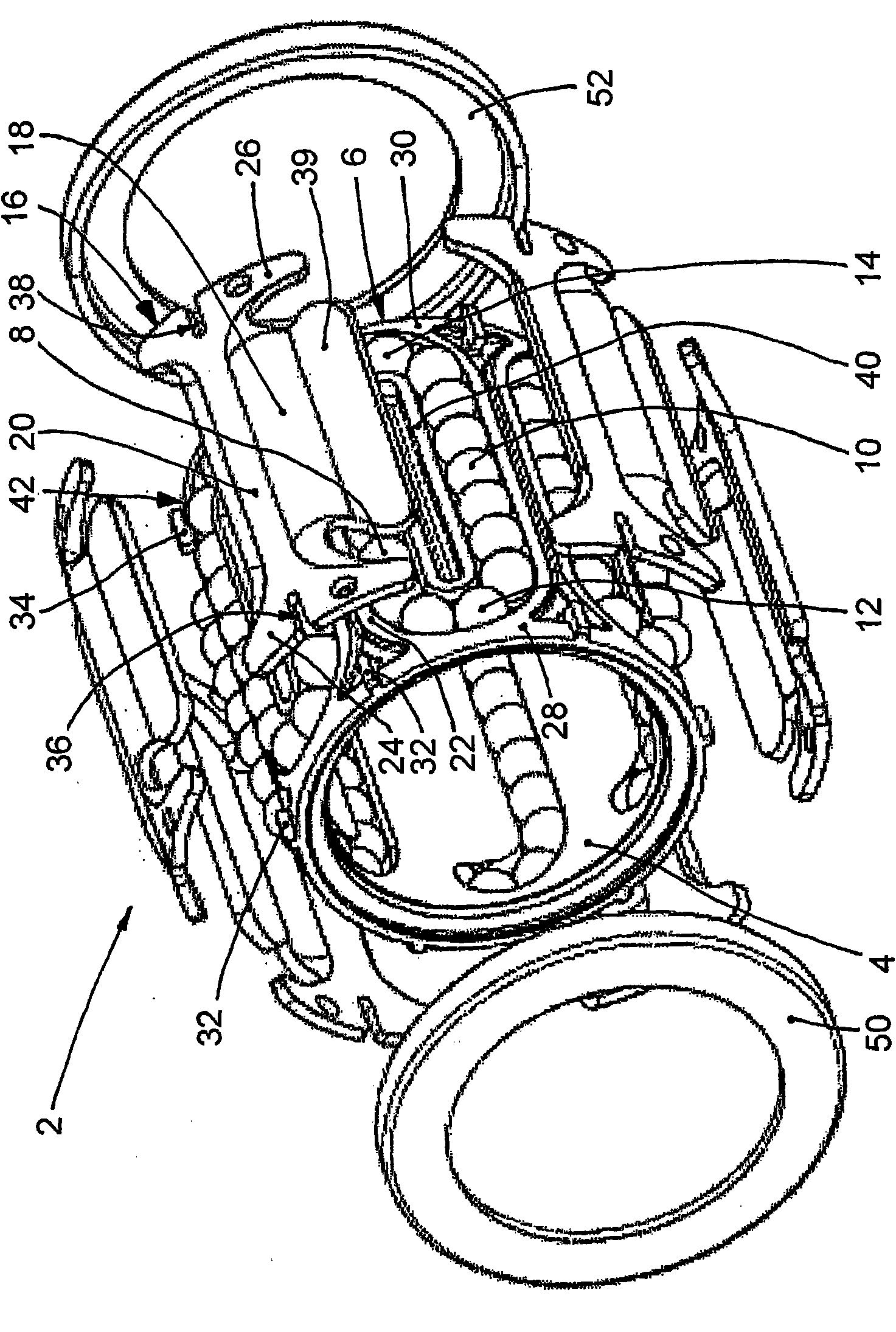
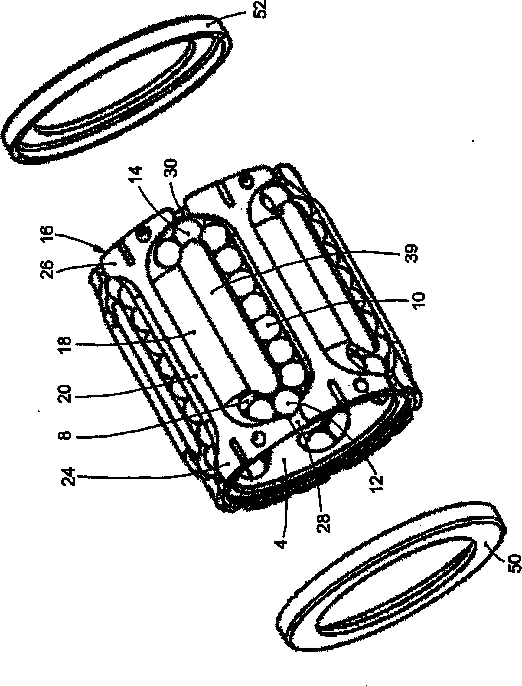
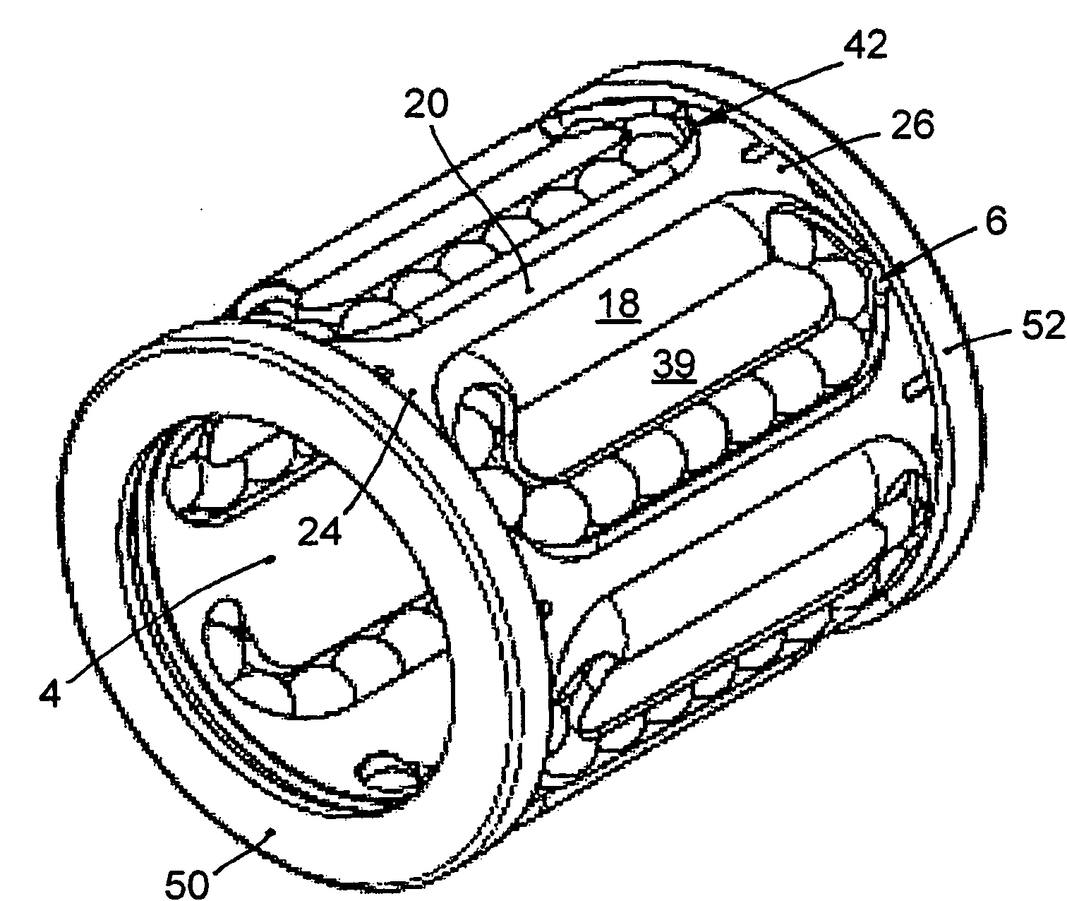
[0025] Figure 1-4 Different assembled states or views of preferred embodiments of the invention are shown.

[0026] The linear ball bearing 2 comprises a substantially sleeve-like cage 4 for accommodating a plurality (six in this embodiment) of axial ball races distributed over the circumference of the cage, wherein each ball race comprises a A first raceway open radially inwards and outwards for the bearing ball row and a radially outwardly opening second raceway for the unsupported ball row and a diversion way interconnecting the raceways of the ball rings. Such cages are known per se and therefore need not be described in detail here.

[0027] The individual ball races of the linear ball bearing 2 are constructed identically, so that the invention will be explained in more detail below with reference to a ball race 6 . The ball race 6 is formed by bearing balls 8 in a first raceway, unsupported balls 10 in a second raceway and balls 12 or 14 in a deflection track. The f...


PUM


Abstract

The present invention relates to a linear ball bearing (2) comprising a substantially sleeve-like cage (4) for receiving a plurality of axial ball loops (6) that are distributed across the circumference of the cage, wherein each ball loop has a first ball channel that is open radially to the inside and to the outside for the row of the carrying ball (8), and a second ball channel, open radially towards the outside for the row of the non-carrying balls (10) and comprises deflection channels that connect the ball channels of a ball loop (6) to each other, and wherein at least the first ball channel is covered on the outside by a load-bearing carrier plate (16). Individual support surfaces (20, 39) are provided on the carrier plates (16), said surfaces resting on predetermined support regions (22, 40) on the outer lateral surface of the cage (4). The carrier plates (16) are positioned via interacting positioning means (32, 34; 36, 38) in the predetermined positions thereof on the cage (4). The carrier plates (16) resting against the cage (4) are fixed to the cage (4) via holding rings (50, 52) that are slid over the carrier plates.

Description

technical field [0001] The invention relates to a linear ball bearing having a substantially sleeve-type cage for accommodating a plurality of axial ball races distributed over the circumference of the cage, wherein each ball race comprises a A first radially inwardly and outwardly open raceway and a second radially outwardly open raceway for the unsupported ball row and a deflection way interconnecting the raceways of the ball ring, and wherein at least the first raceway The outside of the track is covered by a load bearing support plate. Background technique [0002] The function of linear ball bearings is to longitudinally displaceably support a shaft or such component relative to a stationary object or to axially displaceably guide an object on a fixed shaft. The balls in the first raceway of each ball ring in the first race of the linear ball bearing according to the classification are directly attached to the shaft to be supported, receive the force on the bearing and...

Claims


Application Information

Patent Timeline
Patent Type & Authority Applications(China)
IPC IPC(8): F16C29/06
CPCF16C29/069F16C29/0602
Inventor 乌多·克莱因
Owner SCHAEFFLER TECH AG & CO KG
Learn More