
Ring spinn machine with a bundle device

A technology of ring spinning machine and clustering device, which is applied in the direction of continuous winding spinning machine, spinning machine, textile and paper making, and can solve the problems of yarn quality reduction and thread breakage

Inactive Publication Date: 2009-07-08
ZHUOLANG INTELLIGENT MACHINERY CO LTD
View PDF3 Cites 0 Cited by
  • Summary
  • Abstract
  • Description
  • Claims
  • Application Information

AI Technical Summary

Problems solved by technology

However, it has been found that very slight fiber accumulations can form on the edges of the pad with this protective surface, which can loosen freely and can cause thick spots in the yarn.
Such thick places reduce the quality of the yarn and may lead to thread breakage in subsequent processing

Method used


Image

  • Ring spinn machine with a bundle device
  • Ring spinn machine with a bundle device

Examples


Embodiment Construction

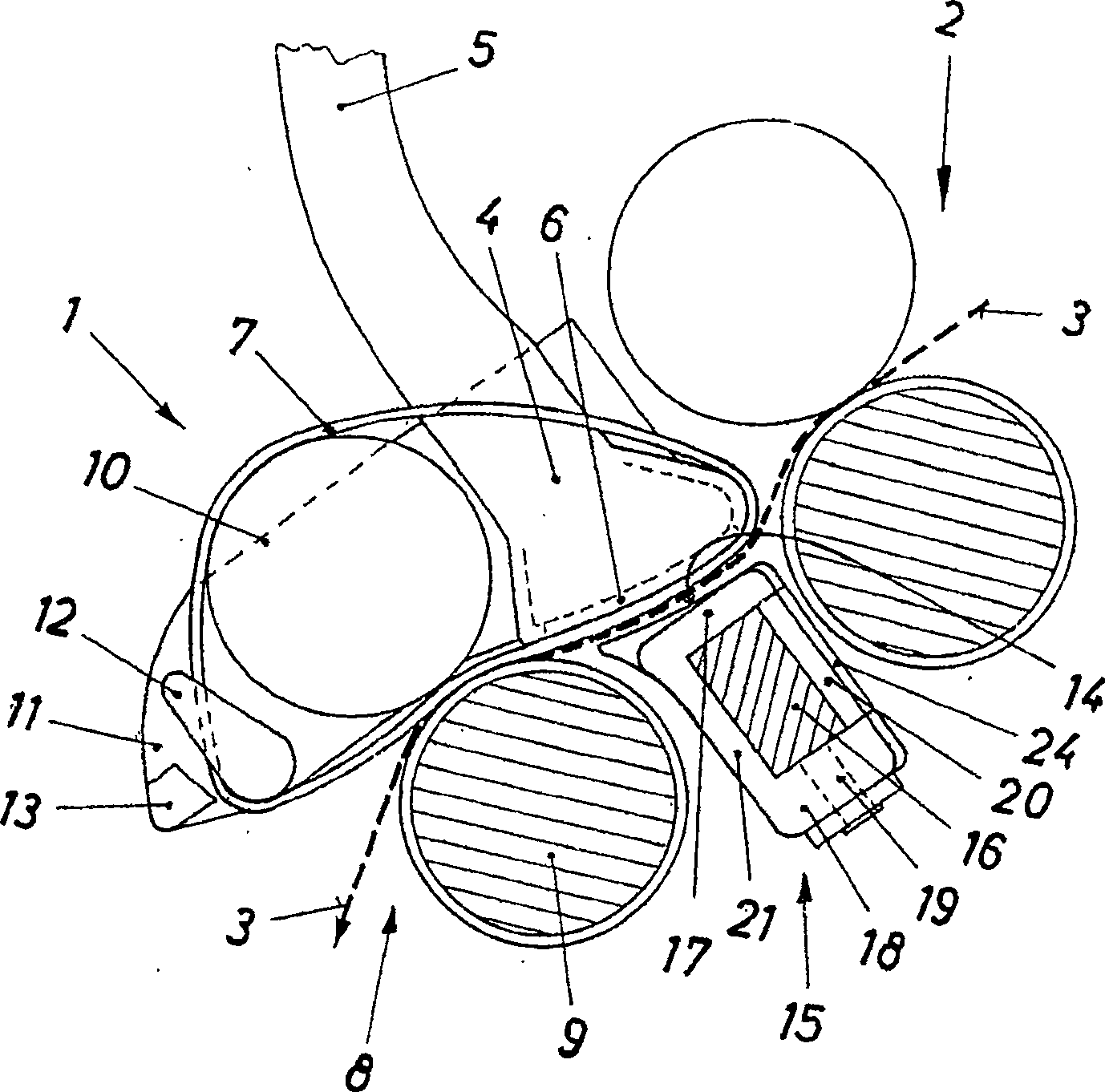
[0012] The bundling device 1 is of a known construction. It comprises a suction shoe 4 which is connected via a suction line 5 to a suction device (not shown here). The suction shoe 4 has on its underside a suction opening 6 through which a compact belt 7 is guided. Perforated grooves of smaller suction holes run around the circumference of the compact belt, which perforated grooves are guided through the suction holes 6 . If the bundle belt 7 is driven by a pair of rollers 8, it is driven by the lower rollers 9 of all drafting devices of the ring spinning machine, while its upper roller 10 is supported and loaded by an upper roller not shown here. The slats are spring loaded against the bottom rollers.

[0013] The suction shoe 4, the top roller 10 and the closing belt 7 are guided in a cage 11 which is likewise fastened to the support and load slats and has guide clips 12 and a stripping belt for the closing belt slats13.

[0014] Opposite the suction opening 6 of the su...


PUM


Abstract

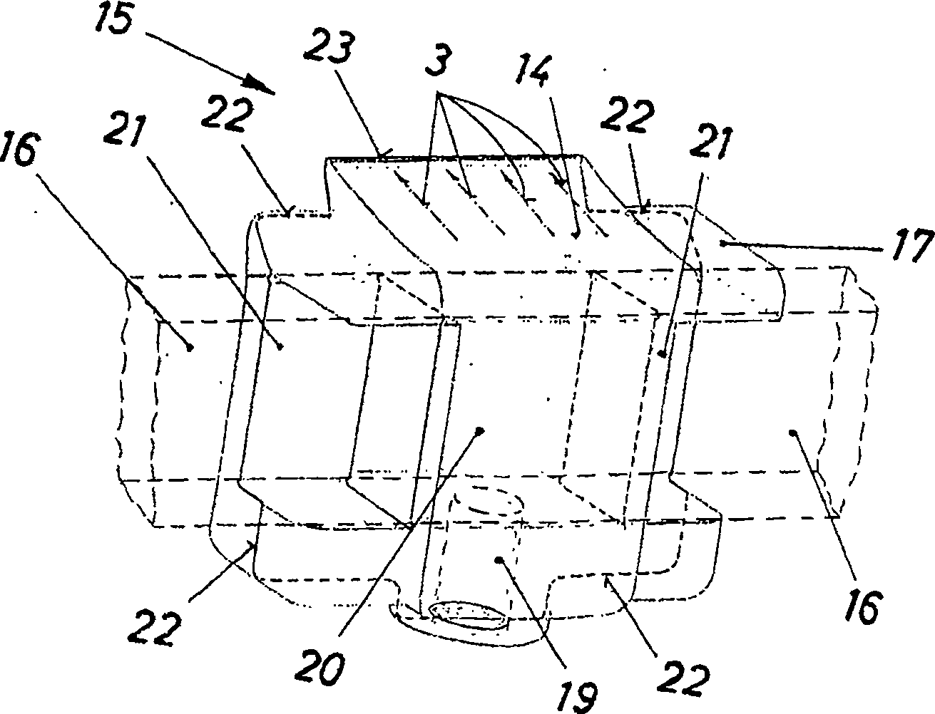
The invention relates to a bundling device for bundling fiber strands in a ring spinning machine, which has a protective surface (14) in the material line (3) for the bundling area. In order to avoid the formation of fiber accumulations on this protective surface, it is provided that the protective surface and the liner (15) supporting the protective surface are produced as plastic injection-molded parts, all of its edges opposite to the material flow are rounded, and the die-casting mold The parting line (22) is arranged such that it does not lie in the material flow.

Description

technical field [0001] The invention relates to a ring spinning machine with constricting devices, each of which comprises a converging belt with at least one perforated groove, which runs on a suction shoe and a protective surface Opposite thereto, the protective surface is formed on a liner which is arranged on a support rail extending along the cluster. Background technique [0002] This closing device is used to suck up lifted fibers onto the roving and thus prevent fuzzing of the produced yarn. This also increases the breaking strength of the yarn and improves its processability into woven or knitted fabrics. [0003] The protective surface belonging to the concentrating region can protect the concentrating region from disturbing air turbulence caused, for example, by traveling cleaners. However, it has been found that very slight fiber accumulations can form on the edges of the pads with this protective surface, which can loosen freely and can lead to thick places in...

Claims


Application Information

Patent Timeline
IPC IPC(8): D01H5/86D01H1/02D01H5/26D01H5/72
CPCD01H5/72D01H5/26
Inventor J·斯梅卡尔S·克拉维茨
Owner ZHUOLANG INTELLIGENT MACHINERY CO LTD
Learn More