Electric vehicle capable of being charged during travelling process
An electric vehicle, driving technology, applied in the direction of electric vehicles, collectors, electric traction, etc., can solve the problems of limited electric energy charged by the storage battery, limit the consumption of electric vehicles, and cannot travel long distances, etc., to achieve fast response and structural design Simple and reasonable, improve the effect of long-distance travel
- Summary
- Abstract
- Description
- Claims
- Application Information
AI Technical Summary
Problems solved by technology
Method used
Image
Examples
Embodiment 1
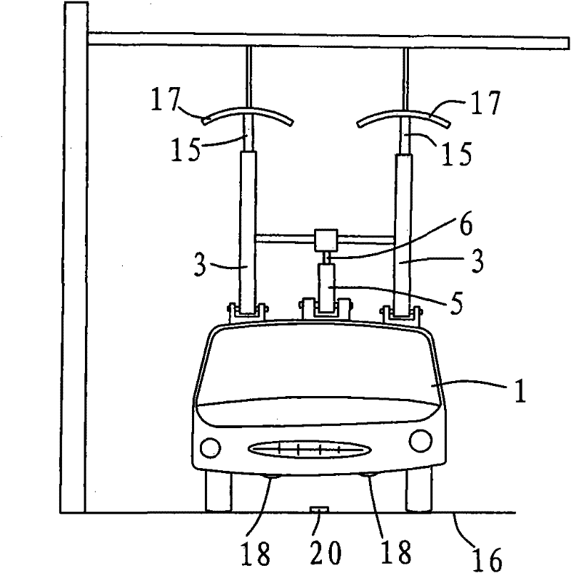
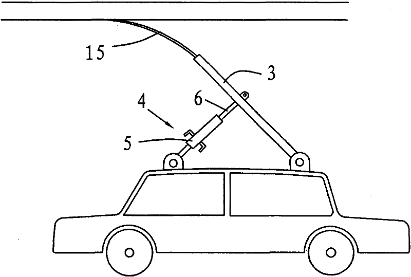
[0028] Embodiment 1, combining Figure 1 to Figure 8 , an electric vehicle, comprising a car body 1 and a storage device 2, the top of the car body 1 is provided with a guide rod 3 and a pneumatic telescopic rod 4, the pneumatic telescopic rod 4 includes a bottom cover 5 and a piston 6, the bottom of the bottom cover 5 is connected to the The car body 1 is hinged, the top of the piston 6 is movably connected with the guide rod 3, the bottom of the bottom cover 5 is provided with an air inlet pipe 7 and an air exhaust pipe 8, and the air outlet pipe 8 is provided with a normally open solenoid valve 9, and the air inlet pipe 7 is arranged in reverse order. There are a normally closed solenoid valve 10, a pressure storage tank 11, a pressure switch 12, an air pump 13, and a one-way valve 14. In the power-on state, the normally closed solenoid valve 10 is opened, the normally open solenoid valve 9 is closed, the bottom cover 5 is inflated, and the power is turned off. In the norma...
Embodiment 2
[0029] Example 2, combined with Figure 1 to Figure 6 and Figure 8 , Figure 9 The only difference between embodiment 2 and embodiment 1 is that the sensor is an optical solid-state image sensor 30 (CCD for short), and the optical solid-state image sensor 30 is arranged on the longitudinal axis line of the bottom of the vehicle body 1, and is arranged around the optical solid-state image sensor 30. There is an illumination light source 31, and a signal line 32 sensed by an optical solid-state image sensor is arranged on the center line of the charging lane 16. When the optical solid-state image sensor 30 senses that the longitudinal axis of the vehicle body deviates from the center line of the lane, the steering wheel steering assist device 19 will correct it. If the driving direction of the car body is due to actively driving away from the charging lane, the optical solid-state image sensor senses a certain degree of deviation from the center line or the signal of the cente...
Embodiment 3
[0030] Example 3, combined with Figure 10 The difference between embodiment 3 and embodiment 1 is that the hydraulic telescopic rod replaces the pneumatic telescopic rod, the hydraulic telescopic rod includes a bottom cover 40 and a piston 41, the bottom end of the bottom cover 40 is hinged with the vehicle body, and the top of the piston 41 is flexibly connected with the guide rod 3 , the bottom of the bottom cover 40 is provided with an oil inlet pipe 42 and an oil discharge pipe 43, the oil discharge pipe 43 is provided with a normally open solenoid valve 44, and the reverse direction of the oil inlet pipe 42 is provided with a normally closed solenoid valve 45, a pressure storage tank 46, a pressure switch 47, and an oil pump 48. One-way valve 49, in the power-on state, the normally closed solenoid valve 45 is opened, the normally open solenoid valve 44 is closed, the bottom cover 40 is filled with oil, and in the power-off state, the normally closed solenoid valve 45 is c...
PUM
 Abstract
Description
Claims
Application Information
 - R&D
- Intellectual Property
- Life Sciences
- Materials
- Tech Scout
- Unparalleled Data Quality
- Higher Quality Content
- 60% Fewer Hallucinations
Browse by: Latest US Patents, China's latest patents, Technical Efficacy Thesaurus, Application Domain, Technology Topic, Popular Technical Reports.
© 2025 PatSnap. All rights reserved.Legal|Privacy policy|Modern Slavery Act Transparency Statement|Sitemap|About US| Contact US: help@patsnap.com


