Evaporation heat transfer pipe

A technology of heat transfer tubes and outer fins is applied in the field of heat transfer tubes to achieve the effects of improving heat transfer efficiency, enhancing boiling heat transfer, and enhancing evaporation performance

Active Publication Date: 2012-11-21
GOLDEN DRAGON PRECISE COPPER TUBE GROUP
View PDF0 Cites 5 Cited by
  • Summary
  • Abstract
  • Description
  • Claims
  • Application Information

AI Technical Summary

Problems solved by technology

[0004] With the continuous emergence of new working fluids, the properties of each working fluid are different. To make the current concave cavity structure have a stable steam collection ability for different working fluids, and to be able to generate bubbles stably and continuously, is hard to do

Method used


Image

  • Evaporation heat transfer pipe
  • Evaporation heat transfer pipe
  • Evaporation heat transfer pipe

Examples


Embodiment 1

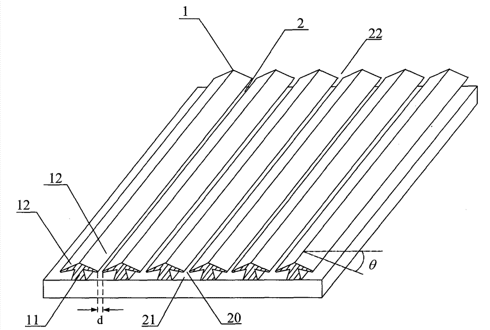
[0026] refer to figure 1 , shows a schematic diagram of the horizontally expanded structure of the first embodiment of the fin portion of the evaporating heat transfer tube. It is assumed that in the present embodiment, the fin portion of the evaporative heat transfer tube is disposed on the outer surface of the evaporative heat transfer tube. Such as figure 1 As shown, the fin portion includes: a plurality of outer fins 1 distributed in parallel, and inter-fin grooves 2 are formed between two adjacent outer fins 1 . Each outer fin 1 includes: a main wing 11 and two secondary wings 12 . The two secondary wings 12 are arranged on the top of the main wing 11, and a certain angle θ is formed between the top and the horizontal end line, and the range of θ can be: 0°≤θ≤90°. When θ=0°, the cross section of the outer fin 1 is T-shaped; when 0°<θ<90°, the two secondary wings 12 are inclined downward respectively, and the cross section of the outer fin 1 is similar to an umbrella sh...

Embodiment 2

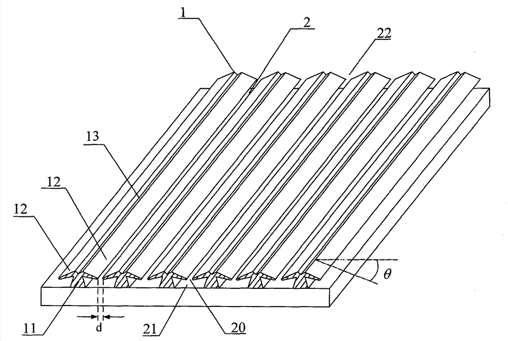
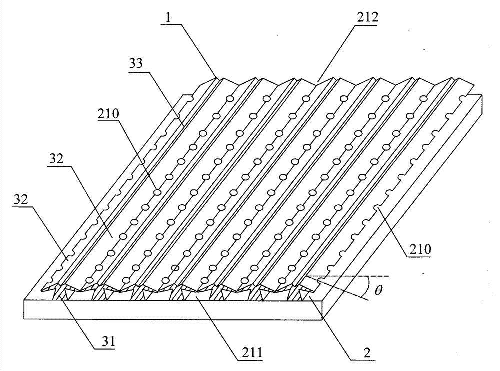
[0032] refer to image 3 , shows a schematic diagram of the horizontally expanded structure of the second embodiment of the fin portion of the evaporating heat transfer tube. Likewise, in this embodiment, it is assumed that the fins of the evaporating heat transfer tubes are disposed on the outer surface of the evaporating heat transfer tubes. Such as image 3 As shown, the fin portion includes: a plurality of outer fins 1 distributed in parallel, and inter-fin grooves 2 are formed between two adjacent outer fins 1 . Each outer fin 1 includes: one main wing 31 and two secondary wings 32 . The two secondary wings 32 are arranged on the top of the main wing 31, and the angle θ formed between the top and the horizontal end line is in the range of: 0°≤θ≤90°. When θ=0°, the cross-section of the outer fin 1 is T-shaped; when 0°<θ<90°, the two secondary wings 32 are inclined downward respectively, and the cross-section of the outer fin 1 is similar to an umbrella shape; When θ=90...


PUM


Abstract

The invention provides an evaporation heat transfer pipe. A fin part of the evaporation heat transfer pipe comprises a plurality of parallel outer fins and inter-fin grooves formed between the outer fins, wherein the cross section of each outer fin is in an approximate umbrella or T shape, and each outer fin comprises a main fin and two sub fins arranged on the top of the main fin, wherein in a horizontal unfolding structure of the fin part, the top end of each sub fin forms a certain included angle with the horizontal end line, a slit flow passage is formed between two adjacent sub fins respectively positioned on two adjacent outer fins, and each inter-fin groove is divided into an upper fin groove and a lower fin groove through the slit flow passage. The evaporation heat transfer pipe provided by the invention increases the heat exchange area exponentially, enhances the turbulence degree of the flowing of fluid, has stable steam gathering capability, can form stable vaporization cores, increases the vaporization core numbers of the heat transfer pipe, and effectively improves the evaporation heat exchange performance of the heat transfer pipe.

Description

technical field [0001] The invention relates to the technical field of heat transfer tubes, in particular to an evaporation heat transfer tube. Background technique [0002] For the heat transfer tube manufacturing industry, improving the energy efficiency of refrigeration and air-conditioning equipment is mainly achieved by developing high-efficiency heat transfer tubes to improve the heat transfer efficiency of heat exchangers. [0003] In the prior art, many kinds of evaporative heat transfer tubes with different structures of outer fins have been developed. Although these evaporative heat transfer tubes with different shapes of outer fins have various structural forms, they all follow the basic principle of boiling enhancement. , That is, most of them are made into concave cavity structures, such as Themoexcel-E tubes, Gewa-T tubes, etc. The concave cavity structure has different wettability and steam collection capacity for different refrigerants, so the evaporation he...

Claims


Application Information

Patent Timeline
Patent Type & Authority Patents(China)
IPC IPC(8): F28F3/02F28F1/12F28F1/40
CPCF28F13/187
Inventor 邓斌吴扬
Owner GOLDEN DRAGON PRECISE COPPER TUBE GROUP
Why Eureka
Try Eureka