Measuring device and method of road mark

A technology of measuring device and measuring method, which is applied in the direction of measuring device, optical device, instrument, etc., can solve the problem of large error of lane width, etc., and achieve the effect of simple principle and algorithm

Inactive Publication Date: 2010-07-14
WUHAN UNIV OF TECH
View PDF0 Cites 40 Cited by
  • Summary
  • Abstract
  • Description
  • Claims
  • Application Information

AI Technical Summary

Problems solved by technology

Its disadvantages and shortcomings are: when the camera tilt and height change due to vehicle bumps, the image acquired through the camera will produce corresponding distortion, and the position of the lane markings in the image will also change at this time. Calibrate and calculate the lane line, and the resulting lane width has a large error

Method used


Image

  • Measuring device and method of road mark
  • Measuring device and method of road mark
  • Measuring device and method of road mark

Examples


Embodiment Construction

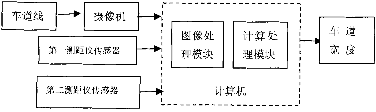
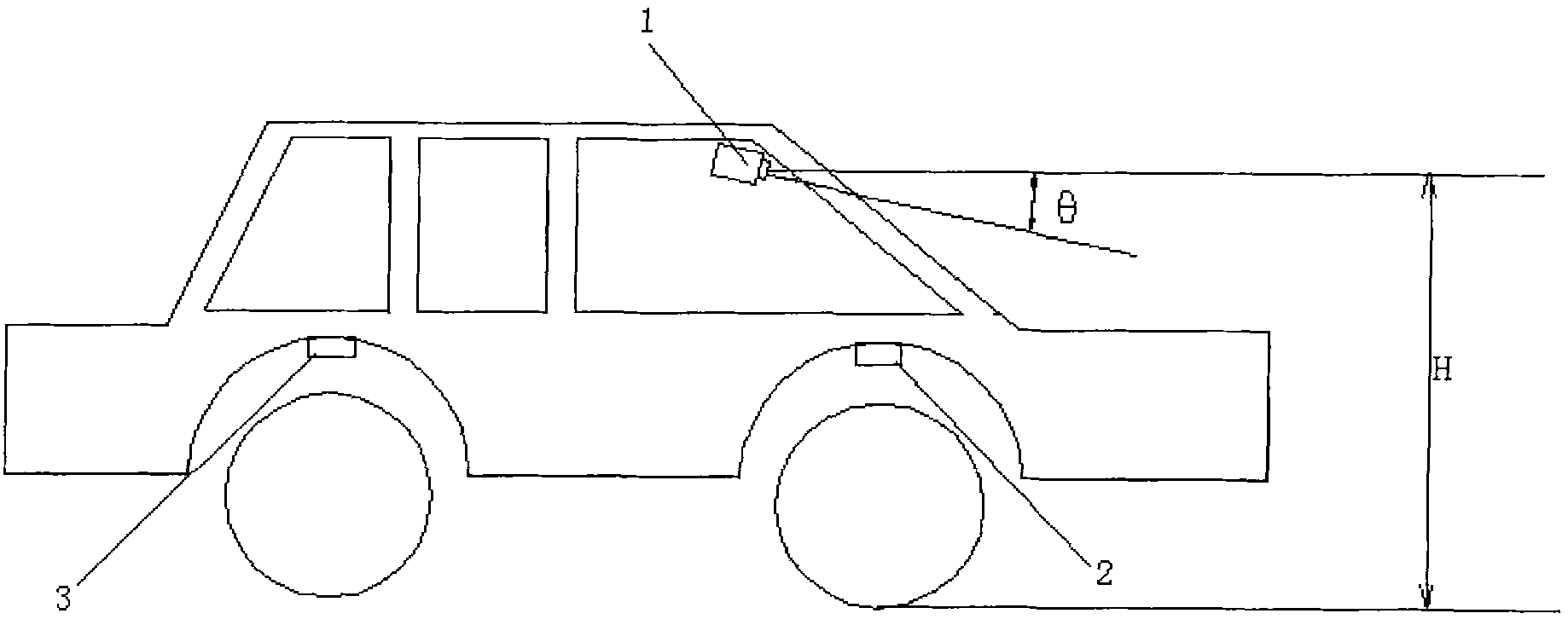
[0015] like figure 2 As shown, the road marking measuring device is installed on a vehicle, and it includes a camera 1, a range finder sensor and a computer. Wherein, the camera 1 is installed in the center of the rear roof of the vehicle windshield, the camera is connected to the computer, and a rangefinder sensor (ie, figure 1 The first range finder sensor 2 and the second range finder sensor 3) in the range finder sensor, the range finder sensor is connected to the computer. like figure 1 As shown, the computer includes an image processing module and a calculation processing module. The first rangefinder sensor 2 measures the vertical distance from the chassis near the front wheels to the ground, and the second rangefinder sensor 3 measures the vertical distance from the chassis near the rear wheels to the ground.

[0016] The steps of the road marking measurement method of the present invention include:

[0017] 1) At the front and rear wheels of the vehicle, the heig...


PUM


Abstract

The invention provides measuring device and method of a road mark. The measuring device comprises a video camera, distance meter sensors and a computer, wherein the video camera is arranged behind a windshield of a vehicle and is connected with the computer; a front wheel and a rear wheel of the vehicle are respectively provided with the distance meter sensors; and the distance meter sensors are connected with the computer. The measuring method comprises the following steps of: (1) respectively collecting the height information of a chassis on the front wheel and the rear wheel by the two distance meter sensors; (2) acquiring a road ahead image by the video camera; and (3) transmitting the collected height information of the chassis and the information of the road ahead image to the computer, wherein the computer outputs the width of a lane ahead of vehicle running through operation. The invention can accurately obtain the width of the lane without being influenced by factors, i.e. vehicle shaking and the like, and has simpler principle and operation.

Description

technical field [0001] The invention relates to the technical field of automobile safety, in particular to a computer vision-based road marking measurement device. Background technique [0002] With the development of vehicle intelligence, fast and accurate identification of navigation paths has become the key to autonomous navigation of intelligent vehicles, and fast and accurate identification of lane markings is particularly important. At present, the vast majority of lane marking measurement methods use the camera installed behind the windshield of the vehicle to obtain the road ahead image under the condition that the camera inclination angle and height are fixed, and the image color transformation is performed on the obtained image. , filtering, grayscale correction and other preprocessing to obtain the region of interest, and then perform image segmentation processing and edge detection-based lane line feature extraction on it, and then use Hough transform, combined w...

Claims


Application Information

Patent Timeline
Patent Type & Authority Applications(China)
IPC IPC(8): G01B11/02
Inventor 吕植勇彭琦严新平程志端陈超
Owner WUHAN UNIV OF TECH
Why Eureka
Try Eureka