Electrical connector

a technology of electrical connectors and connectors, applied in the direction of fixed connections, coupling device connections, coupling parts engagement/disengagement, etc., can solve the problems of electrical contact failure between the contact portion and the flat conductive member, the terminal tends to have an unstable position, etc., to prevent the flux from flowing up thoroughly, and good condition

Active Publication Date: 2010-07-22
HIROSE ELECTRIC GROUP
View PDF5 Cites 14 Cited by
  • Summary
  • Abstract
  • Description
  • Claims
  • Application Information

AI Technical Summary

Benefits of technology

[0032]As described above, in the present invention, the second groove portion corresponds to the second area, which is other than the first area and is provided at least three spots. Accordingly, the second groove portion controls the shift of the second area in the thickness direction of the terminal at three spots arranged over a whole area of the terminal. As a result, the first area is secured at the proper position in the first groove portion. Consequently, the first area obtains the space having a proper width between the plate surface thereof and the inner surface of the first groove portion.
[0033]Therefore, it is possible to prevent the flux from flowing into the first area and to maintain the upper arm portion of the terminal movable. In addition, the flux does not adhere to a surface of the terminal, thereby maintaining the surface of the terminal in good condition. In addition, the first groove portion with the width wider than the thickness of the terminal corresponds to the first area including where the connecting portion is provided in the terminal. Thus the first area obtains the space between the plate surface thereof and the inner surface of the first groove portion. Accordingly, it is possible to prevent the flux from flowing up thoroughly.

Problems solved by technology

As a result, the terminal tends to have an unstable position in the thickness direction thereof, at the wider portion.
Moreover, when the flux reaches the contact portion of the upper arm portion, an electrical contact failure can occur between the contact portion and the flat conductive member.

Method used


Image

  • Electrical connector
  • Electrical connector
  • Electrical connector

Examples


Embodiment Construction

[0039]Hereunder, an embodiment of the present invention will be explained with reference to the accompanying drawings.

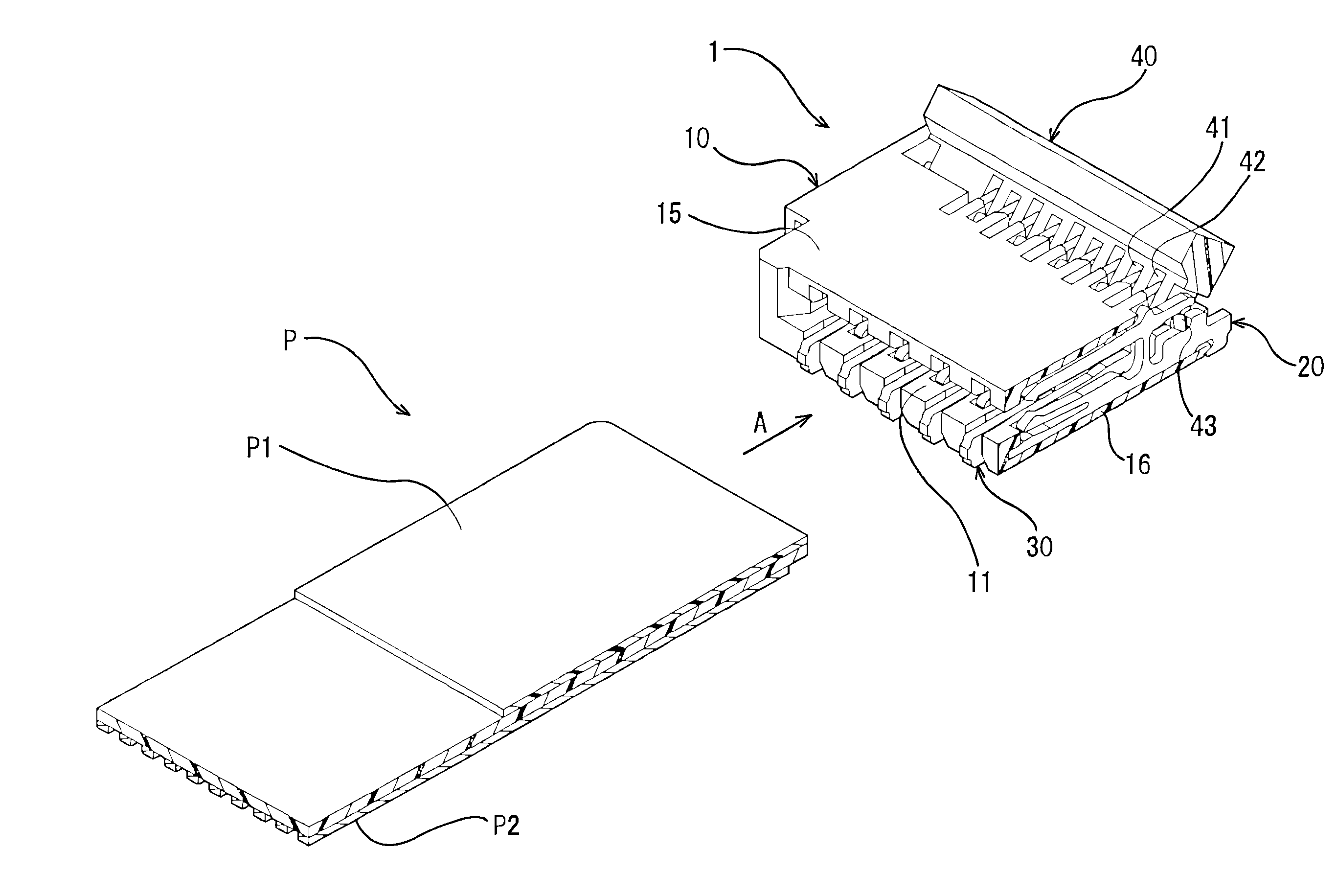
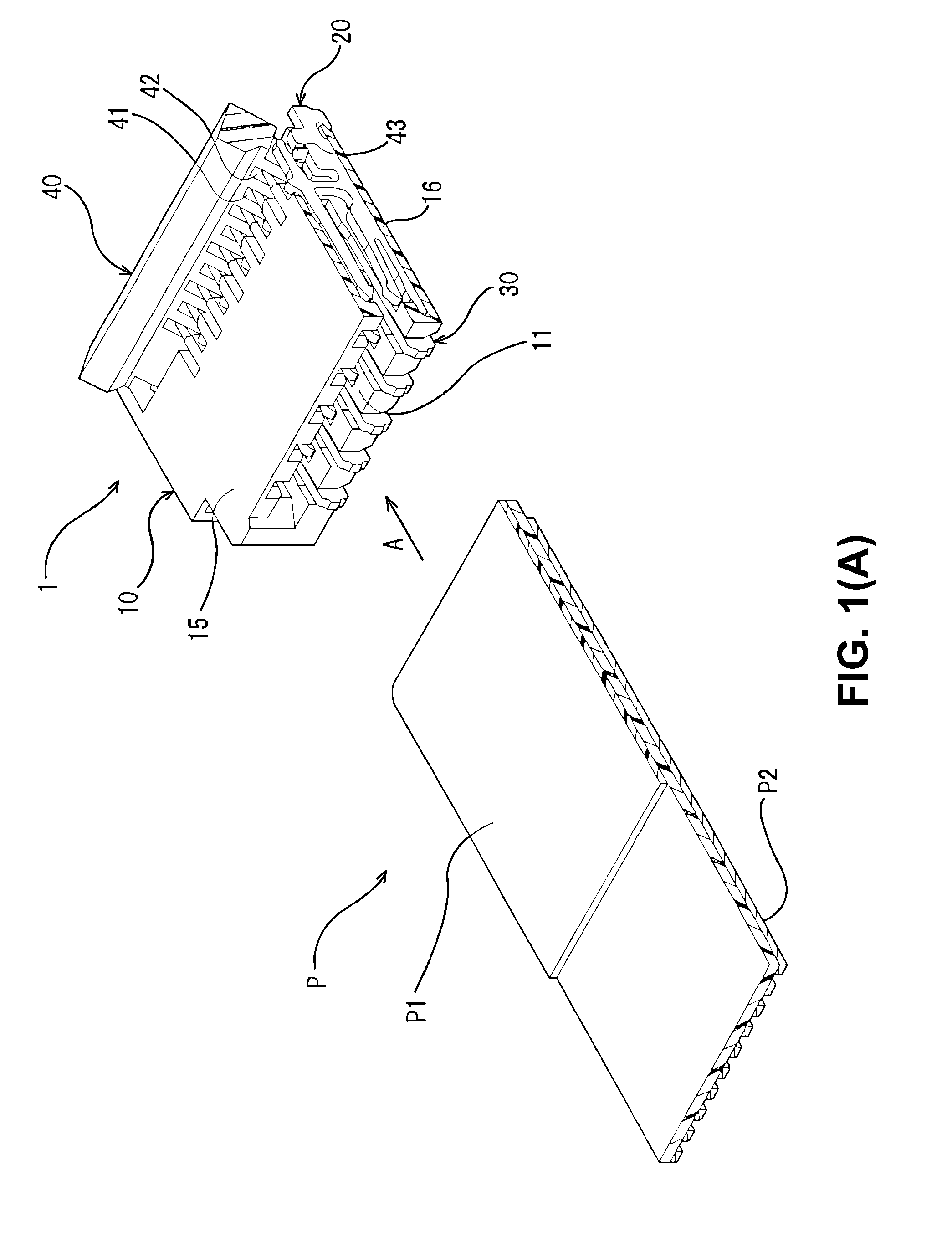
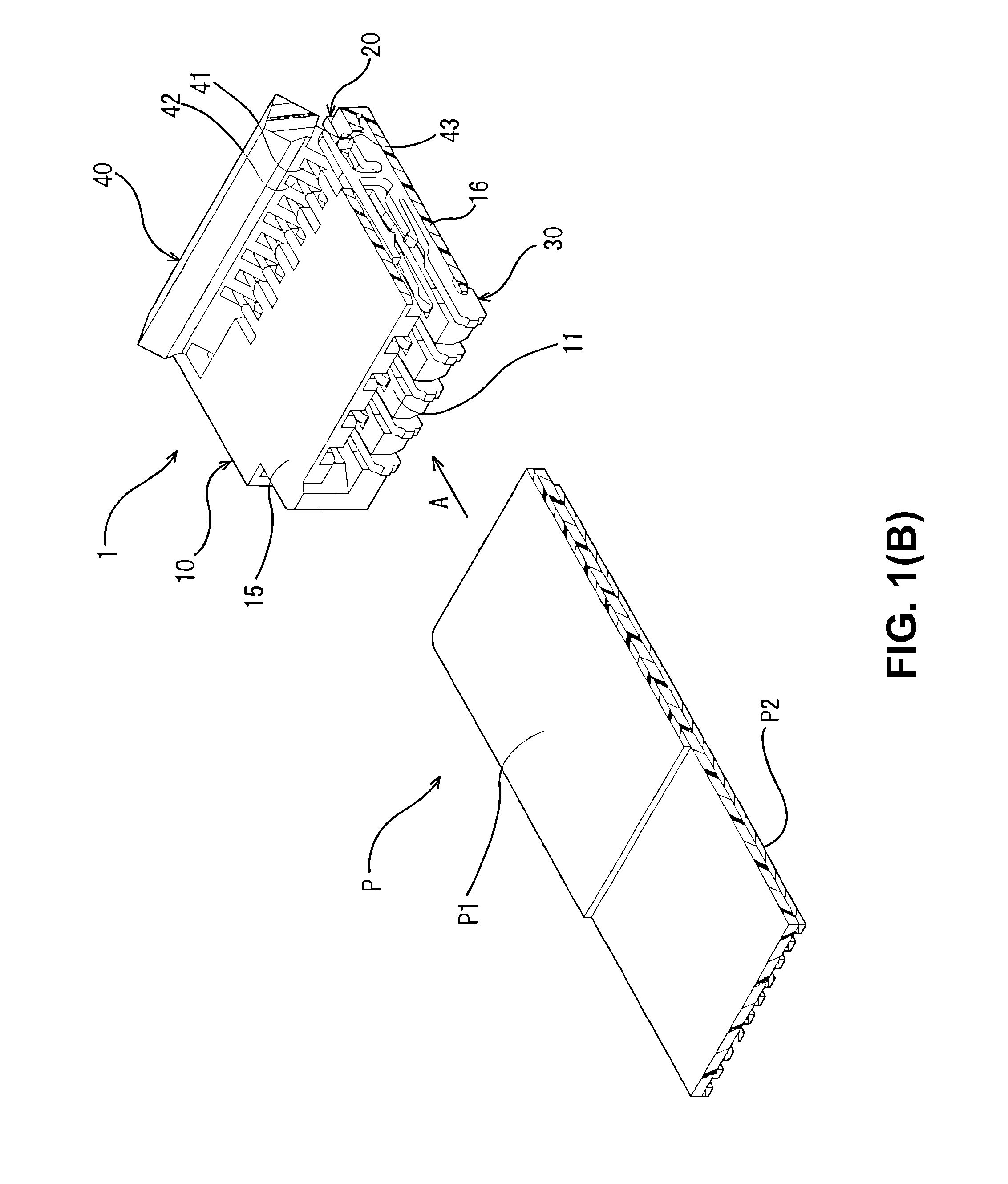
[0040]FIG. 1(A) is a sectional perspective view showing an electrical connector 1 (a connector) for a flat conductive member and the flat conductive member P to be connected to the connector 1, according to an embodiment of the present invention, cut along a plane perpendicular to a direction terminals are disposed (a terminal disposing direction) at a first terminal 20 (described later) is situated. And FIG. 1(B) is a sectional perspective view showing the connector 1 and the flat conductive member P to be connected to the connector 1, cut along a plane perpendicular to the terminal disposing direction at a second terminal 30 (described later) is situated. The first terminal 20 and the second terminal 30 may be referred to as “terminals 20, 30” inclusively, for convenience in explanation.

[0041]In the embodiment, the connector 1 includes a housing 10 made from a synt...


PUM


Abstract

An electrical connector for connecting a flat conductive member includes a housing made of an electrical insulating material and including a terminal holding groove, and a terminal held in the terminal holding groove for contacting with the flat conductive member. The terminal holding groove includes a first groove portion and a second groove portion. The groove portion has a first groove width, and the second groove portion has a second groove width smaller than the first groove width. The terminal includes an upper arm portion, a lower arm portion extending in parallel with the upper arm portion, and a combining portion combining the upper arm portion and the lower arm portion. The lower arm portion includes a connecting portion accommodated in the first groove portion and to be soldered to a circuit board. The upper arm portion includes a pressing portion for pressing the flat conductive member.

Description

BACKGROUND OF THE INVENTION AND RELATED ART STATEMENT[0001]The present invention relates to an electrical connector to be connected to a flat conductive member.[0002]Patent Reference has disclosed a conventional electrical connector (a connector) to be connected to a flat conductive member. According to Patent Reference, the conventional electrical connector includes a housing for receiving the flat conductive member such as a flexible printed circuit board (FPC) and a flexible flat cable (FFC), a plurality of terminals, and an actuator attached to the housing.[0003]The terminals include a plurality of first terminals and a plurality of second terminals. Each of the first terminals and the second terminals is made from a metal plate by punching into an H-character shape substantially so as to maintain a plate surface of the metal plate. The terminals are pressed into and held in the housing so that the plate surfaces thereof are parallel to each other. The actuator is capable of rot...

Claims


Application Information

Patent Timeline
Patent Type & Authority Applications(United States)
IPC IPC(8): H01R13/62H01R12/55H01R12/61H01R12/67H01R12/77H01R12/83H01R12/88H01R24/00H01R24/60
CPCH01R4/028H01R12/57H01R12/62H01R12/79H01R12/88
Inventor SUNAGA, SHIRO
Owner HIROSE ELECTRIC GROUP
Why Eureka
Try Eureka