Optical fiber electric energy meter
A technology of electric energy meter and optical fiber, which is applied in the field of optical fiber electric energy meter, can solve the problems of poor reliability of metering data collection and poor real-time transmission, and achieve the effect of improving the success rate of collection, high real-time performance and ensuring reliability
- Summary
- Abstract
- Description
- Claims
- Application Information
AI Technical Summary
Problems solved by technology
Method used
Image
Examples
Embodiment 1
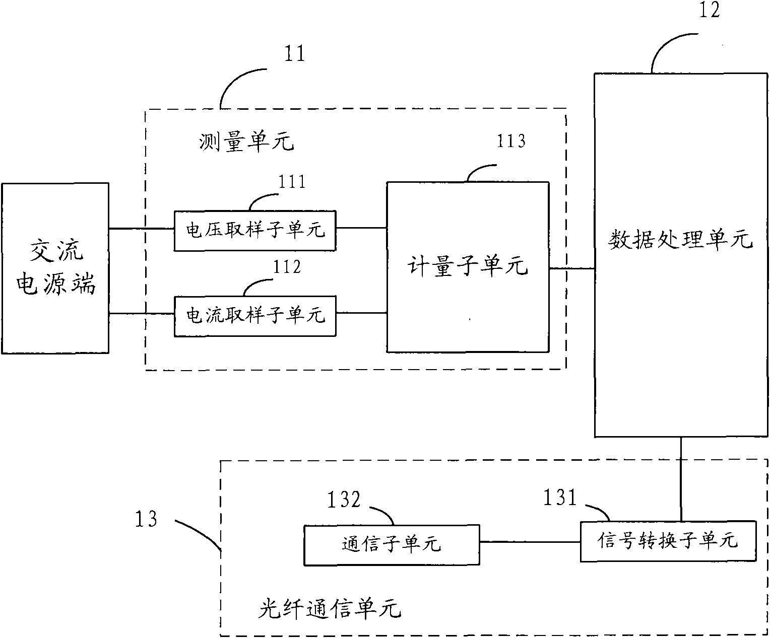
[0040] figure 1 Shown is a schematic structural diagram of an optical fiber electric energy meter provided in Embodiment 1 of the present application. The optical fiber electric energy meter mainly includes a measurement unit 11, a data processing unit 12, and an optical fiber communication unit 13.
[0041] The measuring unit 11 is configured to measure current and voltage data, calculate electricity amount information and electricity cost information according to the measurement results, and send the electricity amount information and electricity cost information to the data processing unit.
[0042] The measurement unit 11 may specifically include: a voltage sampling subunit 111, a current sampling subunit 112, and a measurement subunit 113.
[0043] The voltage sampling subunit 111 is used to measure the voltage data of the AC power terminal. One end is connected to the AC power terminal to collect the voltage data of the AC power terminal, including change data of the total phas...
Embodiment 2
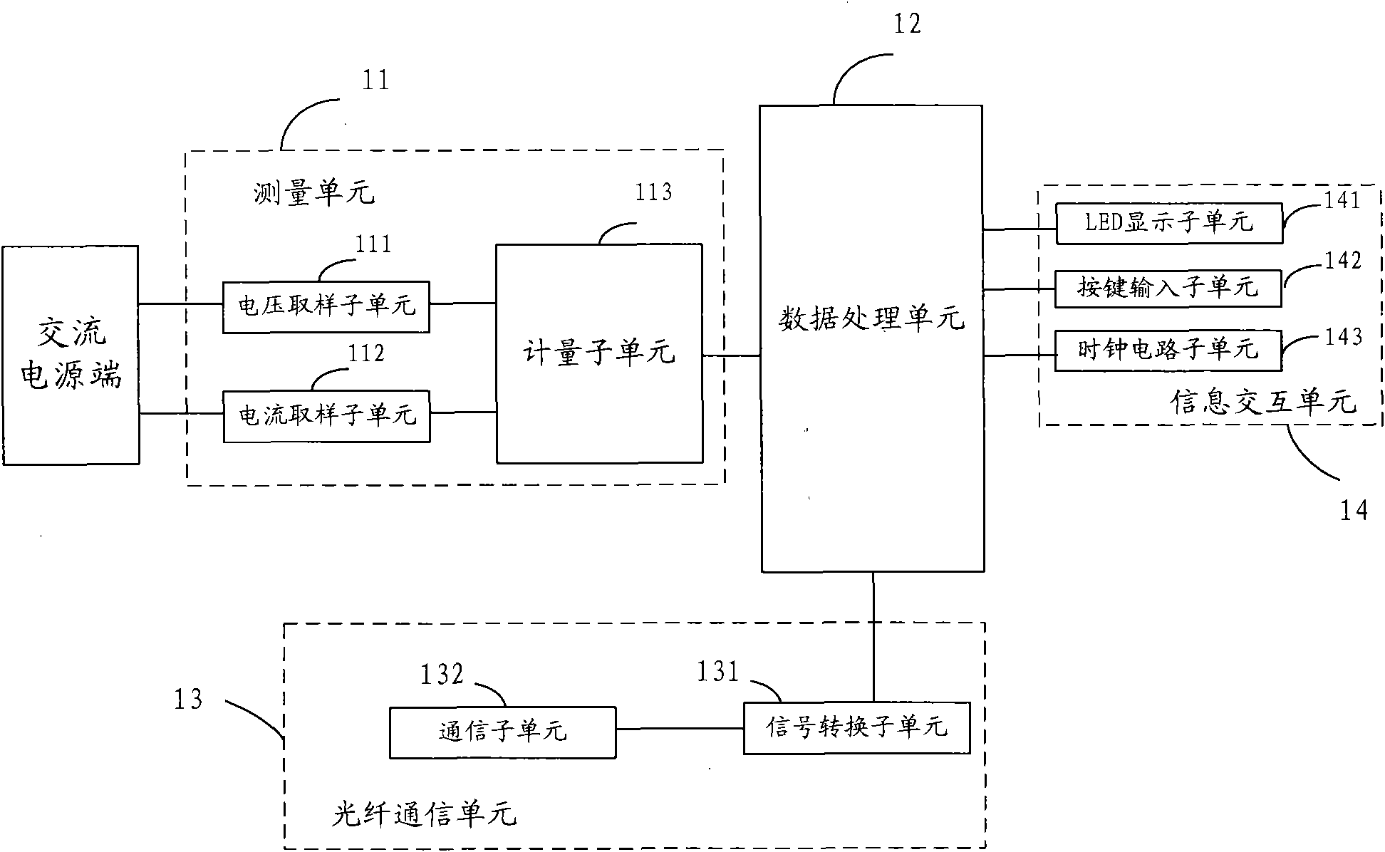
[0054] Such as figure 2 Shown, with figure 1 The difference in the illustrated embodiment is that the optical fiber electric energy meter of this embodiment further includes: an information interaction unit 14 for displaying the processing result of the data processing unit, obtaining the user's operation request, and returning the operation request to the data processing unit 12 .
[0055] The data processing unit 12 is also configured to send the processing result to the information exchange unit 14 and receive and process the operation request sent by the information exchange unit 14.
[0056] The information interaction unit 14 may include: an LED display subunit 141, a key input subunit 142, and a clock circuit subunit 143.
[0057] Wherein, the LED display sub-unit 141 is used to receive and display the processing result sent by the data processing unit 12, and the displayed processing result may include power information and electricity cost information. The display mode of ...
Embodiment 3
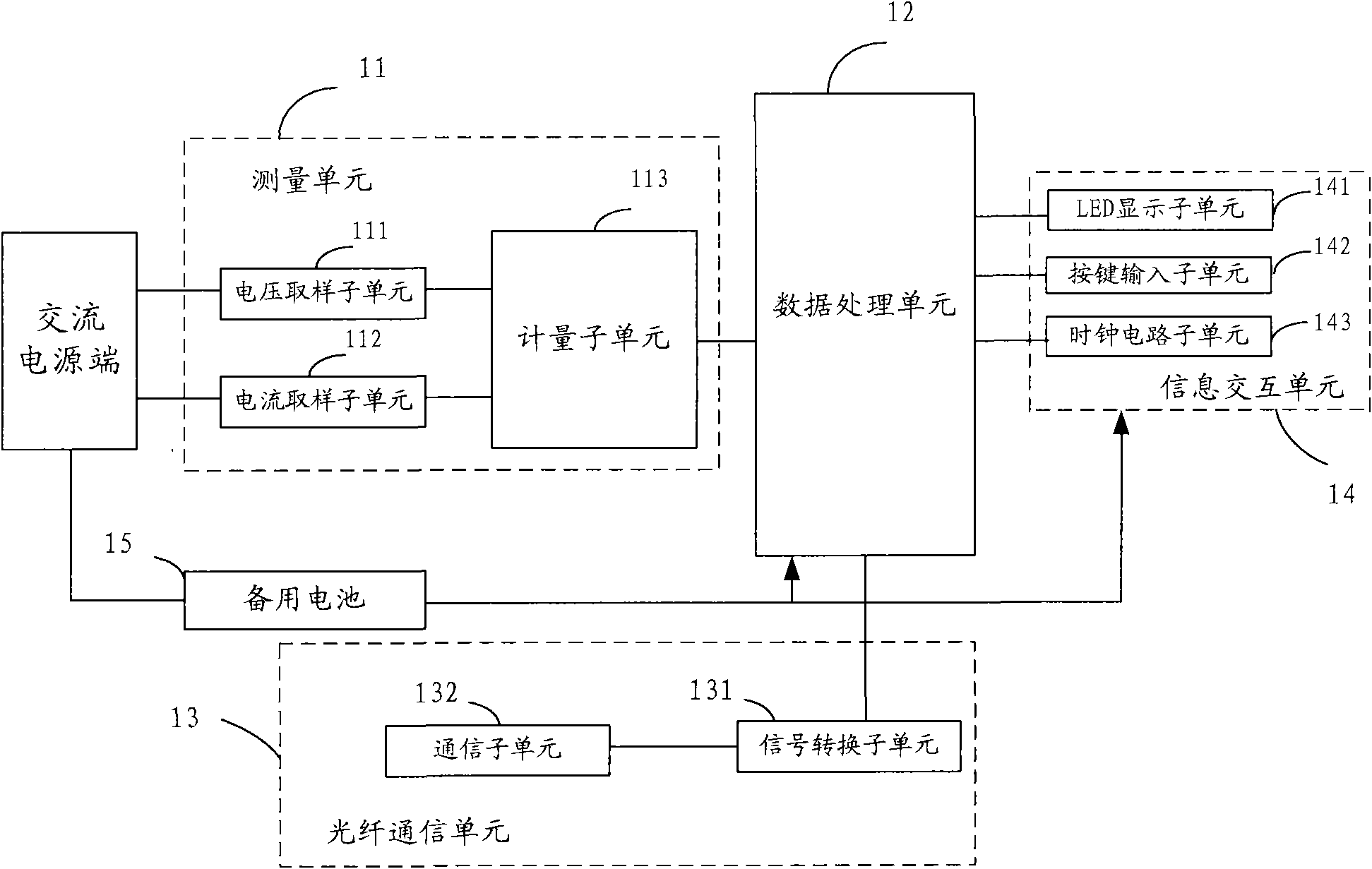
[0062] Such as image 3 Shown, with figure 2 The difference in the illustrated embodiment is that the optical fiber electric energy meter of this embodiment further includes a backup battery 15 for supplying power to the data processing unit 12 and the information interaction unit 14 in the event of a power failure.
[0063] The backup battery 15 can be a rechargeable battery. Under normal power supply conditions, the backup battery 15 is charged by AC power. When the AC power supply cannot be supplied, the backup battery 15 supplies power to the data processing unit 12 and the information interaction unit 14, so in the event of a power failure It has a wake-up display function to ensure that the information interaction unit 14 can still display power information and electricity cost information, which is convenient for staff or users to read the meter when the power is out. In addition, those skilled in the art should know that the use of rechargeable batteries is only a specifi...
PUM
 Abstract
Description
Claims
Application Information
 - R&D
- Intellectual Property
- Life Sciences
- Materials
- Tech Scout
- Unparalleled Data Quality
- Higher Quality Content
- 60% Fewer Hallucinations
Browse by: Latest US Patents, China's latest patents, Technical Efficacy Thesaurus, Application Domain, Technology Topic, Popular Technical Reports.
© 2025 PatSnap. All rights reserved.Legal|Privacy policy|Modern Slavery Act Transparency Statement|Sitemap|About US| Contact US: help@patsnap.com


