Storage rack arrangement for the storage of nuclear fuel elements

A technology for nuclear fuel elements and fuel elements, which is applied in the fields of reactor fuel elements, nuclear engineering, nuclear power generation, etc., can solve the problems of shaking, reducing the stability of storage racks, high impact force, etc. Effect

Inactive Publication Date: 2010-07-14
CCI AG (CH)
View PDF9 Cites 5 Cited by
  • Summary
  • Abstract
  • Description
  • Claims
  • Application Information

AI Technical Summary

Problems solved by technology

This principle allows the elimination of locally extremely high peak loads at the anchorage or support points of the storage rack, but has specific disadvantages
[0009] One disadvantage is that earthquake-induced shifting of storage racks requires a certain amount of free space around the storage racks
This equates to a loss of very expensive storage area
[0010] Another disadvantage is that these displacements lead to irregular spacings of different sizes between the support racks and, after an earthquake, an irregular arrangement of the storage racks may thus occur, which may lead to problems related to the subsequent handling of the stored fuel elements. question
[0011] A further disadvantage arises from the fact that partially loaded and especially unilaterally loaded storage racks are excited to shake at high horizontal seismic accelerations, and the feet of the storage racks may e.g. rise 10 to 20 mm from the floor of the storage tank
This shaking of the storage rack creates a very high impact force on the floor of the storage pool, thereby significantly increasing the risk of a storage pool leak
In addition, an increased tendency of the storage rack to shift in the direction of the unloading position was also observed, which additionally reduces the stability of the storage rack

Method used


Image

  • Storage rack arrangement for the storage of nuclear fuel elements
  • Storage rack arrangement for the storage of nuclear fuel elements
  • Storage rack arrangement for the storage of nuclear fuel elements

Examples


Embodiment Construction

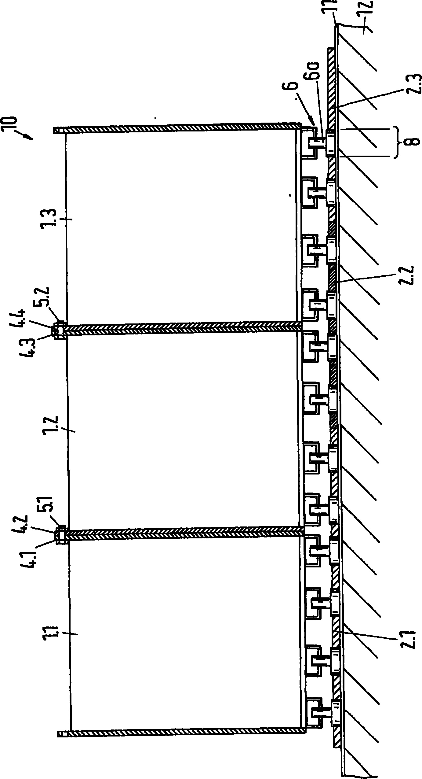
[0029] for storing nuclear fuel elements in storage pools figure 1 The embodiment of the storage rack device 10 shown in includes at least two storage racks 1.1-1.3, and these storage racks each comprise a plurality of vertical passages for receiving fuel elements arranged adjacent to each other, and the positioning elements 6 are arranged on the storage racks. bottom. In addition, the storage racks 1.1-13 arranged adjacent to each other are connected to each other at the top, and the storage rack device 10 also includes one or more bottom plates 2.1-2.3 provided with positioning parts 8, which are aligned with the positioning elements 6 of the storage racks. Cooperate with and position the storage rack relative to the bottom plate together with the positioning element, especially fix the horizontal position of the storage rack relative to the bottom plate, so as to prevent the storage rack from shifting on the bottom plate.

[0030]Advantageously, no fixed connection is prov...


PUM


Abstract

The invention relates to a storage rack arrangement for the storage of nuclear fuel elements. The storage rack arrangement (10) for the storage of nuclear fuel elements in a storage pool includes at least two storage racks (1.1-1.3) which each contain a plurality of vertical channels (9) arranged next to one another for the reception of the fuel elements, with positioning elements (6) being provided at the storage racks at the bottom. The storage racks are connected to one another at the top and the storage rack arrangement (10) additionally includes one or more base plates (2.1-2.3) which are provided with positioning members (8) which fit with the positioning elements (6) of the storage racks (1.1-1.3) and which, together with the positioning elements, position the storage racks with respect to the base plate or base plates (2.1-2.3) to prevent a displacement of the storage racks on the base plate or plates.

Description

technical field [0001] The invention relates to a storage rack arrangement for storing nuclear fuel elements according to the preamble of claim 1 . Background technique [0002] Nuclear fuel elements and in particular spent nuclear fuel elements are stored in storage tanks filled with a coolant such as water which at the same time acts as a shield against radiation of the fuel elements. Spent nuclear fuel elements are kept in storage pools for a long time until they are supplied for reprocessing, or finally disposed of on a case-by-case basis. In order to safely store nuclear fuel elements, storage racks have been developed, wherein a storage pool can accommodate a plurality of storage racks, which can be arranged side by side and on top of each other depending on the respective circumstances. [0003] A storage rack for storing nuclear fuel elements is known from document DE 2930237 A1, comprising a plurality of vertical shafts or channels for receiving fuel elements, the ...

Claims


Application Information

Patent Timeline
Patent Type & Authority Applications(China)
IPC IPC(8): G21C19/07
CPCG21C19/07Y02E30/30
Inventor S·基尔博维奇
Owner CCI AG (CH)
Why Eureka
Try Eureka