Nozzle device of linear cutting machine
A wire cutting machine tool and nozzle device technology, applied in attachments, electric processing equipment, metal processing equipment and other directions, can solve the problems of affecting the surface quality of workpiece processing, unsuitable for automatic production, reducing processing efficiency, etc., and achieve good jet flow effect, The effect of improving the quality of the machined surface and improving the work efficiency
- Summary
- Abstract
- Description
- Claims
- Application Information
AI Technical Summary
Problems solved by technology
Method used
Image
Examples
Embodiment 1
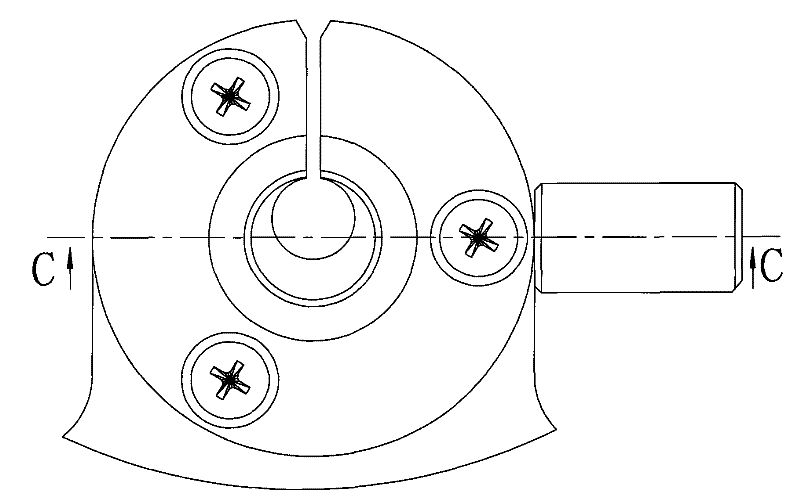
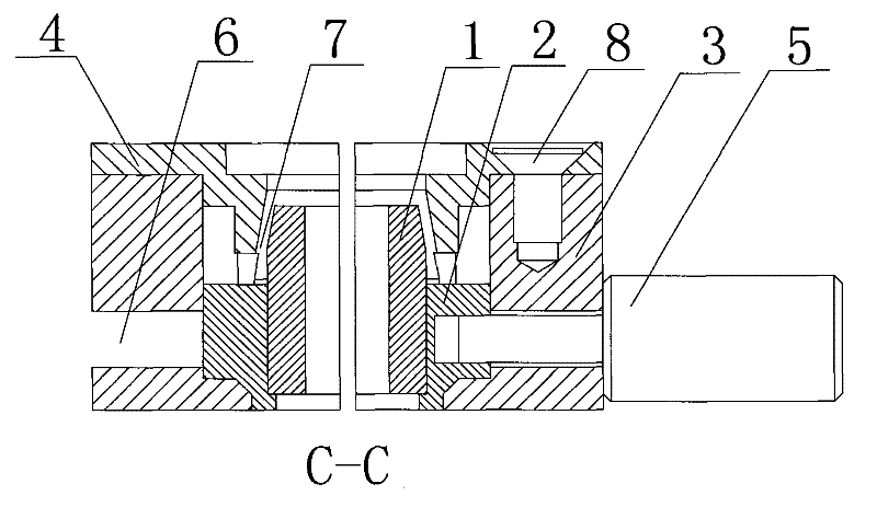
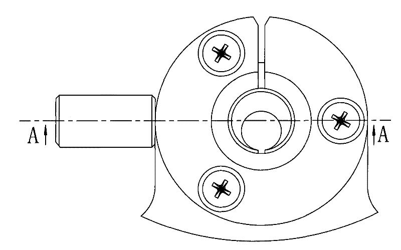
[0018] Embodiment 1: a nozzle device of a wire cutting machine tool, such as figure 2 , Figure 4 As shown, it includes a nozzle seat 2 and a nozzle head 1. The nozzle head 1 is an eccentric cylindrical sleeve structure. One end of the nozzle head 1 is set in the nozzle seat 2. The nozzle seat 2 is installed in the nozzle body 3 to act as a guide wire. function, the nozzle head 1 and the nozzle seat 2 are an interference fit; the nozzle body 3 is provided with a 180° annular groove 6, and the adjusting member 5 is screwed in the annular groove 6, so that The adjustment member 5 is an adjustment screw, the front end of the adjustment screw is fixedly connected with the nozzle seat 2, and the adjustment screw slides in the annular groove 6, and the nozzle seat 2 and the nozzle head 1 are driven by the adjustment screw on the nozzle body 3 Internal rotation; the end of the nozzle body 3 is fixed with a nozzle end cover 4, and the middle of the nozzle end cover 4 is provided wit...
Embodiment 2
[0019] Embodiment 2: A nozzle device for a wire cutting machine tool, including a nozzle seat 2 and a nozzle head 1. The nozzle head 1 is an eccentric cylindrical sleeve structure. One end of the nozzle head 1 is arranged in the nozzle seat 2. The nozzle seat 2 Installed in the nozzle body 3 to act as a guide wire; the nozzle body 3 is provided with a 180° annular groove 6, and an adjusting member 5 is screwed in the annular groove 6, and the adjusting member 5 passes through the nozzle seat 2 Fixedly connected with the nozzle head 1, the adjustment member 5 slides in the annular groove 6, the nozzle seat 2 and the nozzle head 1 rotate in the nozzle body 3 driven by the adjustment member 5; the end of the nozzle body 3 is fixed A nozzle end cover 4 is installed, and a spray outlet 7 forming an annular cavity with the other end of the nozzle head 1 is arranged in the middle of the nozzle end cover 4 . The nozzle end cover 4 is fixed on the nozzle body 3 by three screws 8 .
[...
PUM
 Abstract
Description
Claims
Application Information
 - R&D
- Intellectual Property
- Life Sciences
- Materials
- Tech Scout
- Unparalleled Data Quality
- Higher Quality Content
- 60% Fewer Hallucinations
Browse by: Latest US Patents, China's latest patents, Technical Efficacy Thesaurus, Application Domain, Technology Topic, Popular Technical Reports.
© 2025 PatSnap. All rights reserved.Legal|Privacy policy|Modern Slavery Act Transparency Statement|Sitemap|About US| Contact US: help@patsnap.com


