
Intelligent diagnosis method for bridge telescopic seam injury based on girder end longitudinal displacement

A longitudinal displacement, expansion joint technology, applied in the direction of optical testing flaws/defects, measuring devices, instruments, etc., can solve the problems of poor management and maintenance, affecting traffic, and high costs, reducing labor costs and reducing the possibility of misjudgment The effect of stability and broad engineering application prospects

Inactive Publication Date: 2010-07-21
SOUTHEAST UNIV
View PDF0 Cites 39 Cited by
  • Summary
  • Abstract
  • Description
  • Claims
  • Application Information

AI Technical Summary

Problems solved by technology

Bridge expansion joints bear complex forces and have always been the weak link of bridges. However, due to defects in design and construction, poor management and maintenance, and vehicle overloading, damage to expansion joints in actual engineering is more serious. Therefore, it is necessary to Monitor and evaluate the state of the expansion joints in order to accurately detect the occurrence of damage and repair or replace the expansion joints in time
[0003] At present, the damage detection of expansion joints mainly adopts manual periodic detection, which has the following problems: (1) manual detection is highly subjective, and cannot make quantitative judgments on the damage state of expansion joints; (2) manual Detection usually affects traffic and lacks the accumulation of historical data; (3) the real-time performance is poor, and the occurrence of expansion joint damage cannot be found in time, which may affect the safety of bridge structures and traffic; (4) due to the need for long-term and regular Assign maintenance workers to conduct on-site inspections, the overall cost is higher

Method used


Image

  • Intelligent diagnosis method for bridge telescopic seam injury based on girder end longitudinal displacement
  • Intelligent diagnosis method for bridge telescopic seam injury based on girder end longitudinal displacement
  • Intelligent diagnosis method for bridge telescopic seam injury based on girder end longitudinal displacement

Examples


Embodiment Construction

[0040] Specific embodiments of the present invention are further described below:

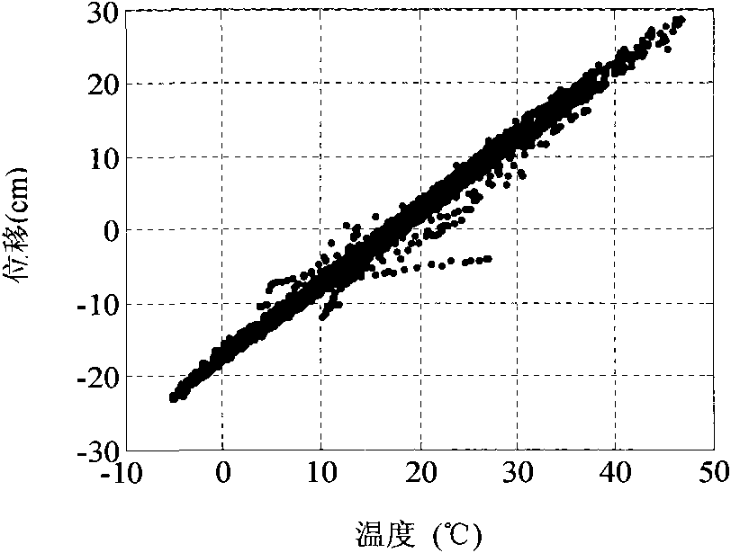
[0041] (1) During the setting process of the longitudinal displacement of the girder end and the environmental condition sensors of the bridge, the number, position and parameter setting of the sensors can be determined according to the specific conditions such as the type of bridge, the span diameter, the bridge deck width and the environment of the bridge site. , usually a longitudinal displacement sensor is set at each end of the main girder, and a temperature sensor and an acceleration sensor are set in the middle of the main girder span, which can meet the needs of the present invention.

[0042] (2) The original monitoring data is processed as follows: the longitudinal displacement of the beam end and the structural temperature data are calculated in a 10-min interval, and the average value is used as the representative value of the longitudinal displacement of the beam end and the structura...


PUM


Abstract

The invention relates to an intelligent diagnosis method for bridge telescopic seam injury based on girder end longitudinal displacement. The long-term monitoring data of main girder longitudinal displacement, temperature and vertical acceleration after a bridge is built are obtained by mounting a small number of sensors on the bridge; a relevance model of the main girder longitudinal displacement, the bridge temperature and the vertical acceleration in a healthy state is established step by step; the influence of the main girder temperature and the vertical acceleration on the longitudinal displacement can be eliminated on the basis of the relevance model, and the environment condition uniformization displacement which can reflect a working state of a telescopic seam is obtained. When the method is applied to the injury diagnosis of the telescopic seam, the monitoring data in an unknown state are processed just by adopting the established relevance model, and finally, the environment condition uniformization displacement of the healthy state and the unknown state is simultaneously input into a mean value control map; and if the telescopic seam generates injury, a sample point of the control map can exceed a control line, thereby realizing the intelligent recognition on the injury of the telescopic seam.

Description

technical field [0001] The invention is an intelligent method applied to damage diagnosis of expansion joints of bridge structures, and relates to the field of non-destructive testing of bridge engineering. Background technique [0002] When the temperature of the bridge changes, the bridge deck has longitudinal deformation of expansion and contraction. In addition, under the action of vehicle load, the bridge deck will also produce longitudinal displacement. In order to meet this deformation, it is necessary to set expansion joints between the beam end of the bridge and the abutment. In the bridge structure, expansion joints must not only meet the longitudinal deformation of the main beam caused by temperature changes and vehicle loads, but also meet the displacement caused by concrete shrinkage and creep, and reduce the secondary deformation of the superstructure caused by uneven settlement. stress [1] Therefore, the expansion joint is a very important structural compone...

Claims


Application Information

Patent Timeline
Patent Type & Authority Applications(China)
IPC IPC(8): G01B11/12G01B11/24G01B11/02G01N21/88
Inventor 丁幼亮邓扬李爱群
Owner SOUTHEAST UNIV
Learn More