Control circuit and method for constant turn-on time transformation circuit

A constant on-time and conversion circuit technology, which is applied in the control/regulation system, DC power input conversion to DC power output, electrical components, etc., can solve the problems of high price and unsuitable volume, and achieve improved performance and good load The effect of response

Active Publication Date: 2010-07-21
CHENGDU MONOLITHIC POWER SYST
View PDF2 Cites 37 Cited by
  • Summary
  • Abstract
  • Description
  • Claims
  • Application Information

AI Technical Summary

Problems solved by technology

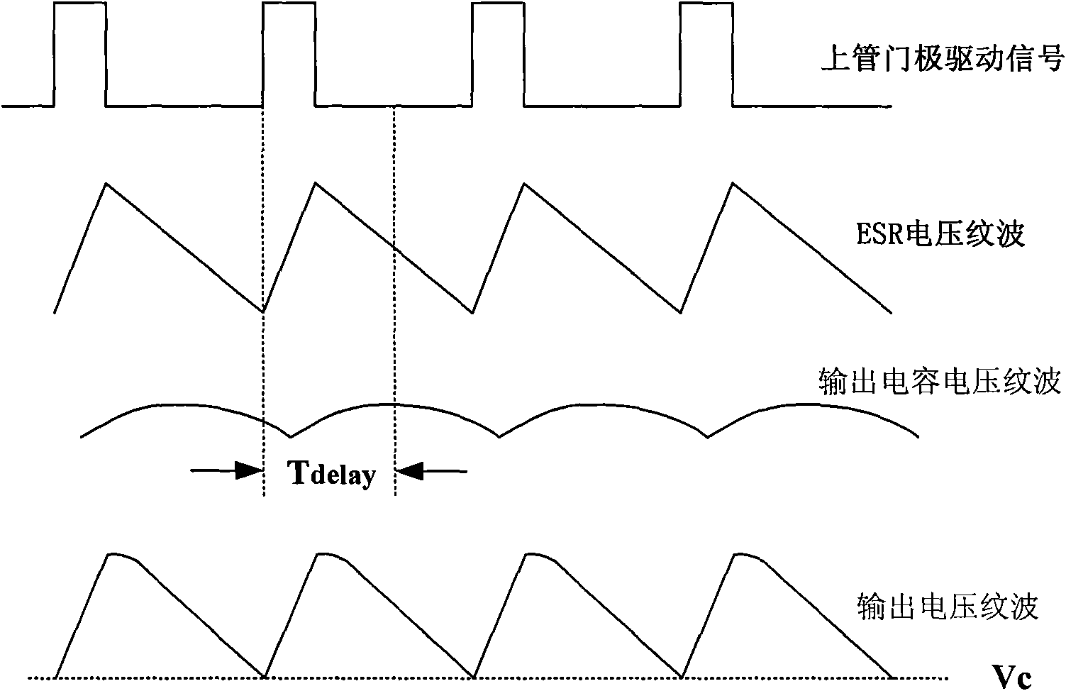
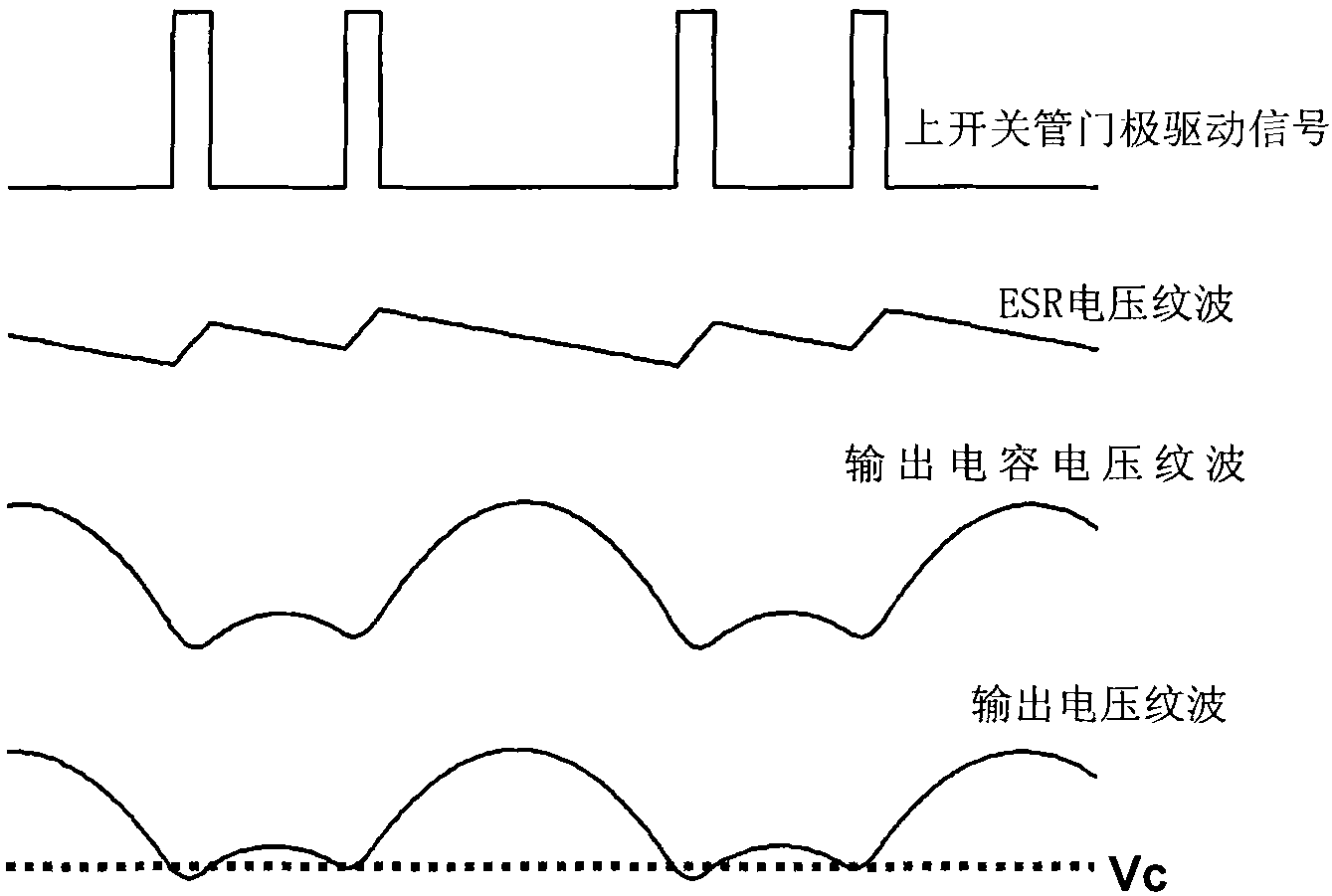
Therefore, in special applications such as notebook computers, traditional constant on-time DC conversion circuits cannot use small and cheap ceramic capacitors as output capacitors, but need to use relatively expensive polymer organic semiconductor solid capacitors (sp- cap)

Method used


Image

  • Control circuit and method for constant turn-on time transformation circuit
  • Control circuit and method for constant turn-on time transformation circuit
  • Control circuit and method for constant turn-on time transformation circuit

Examples


Embodiment Construction

[0023] Such as image 3 As shown, it is a flow chart of an improved constant on-time DC conversion method according to the present invention. When the circuit starts to operate, a feedback signal V FB and a compensation signal V slope The algebraic sum with a reference signal V R Compare. When the feedback signal V FB with compensation signal V slope The algebraic sum is greater than the reference signal V R when V FB +V slope >V R When , keep the current switching state of the output stage of the circuit; when the feedback signal V FB with compensation signal V slope The algebraic sum of is less than the reference signal V REF when V FB +V slope R When, the upper switching tube M of the output stage of the circuit is 1 Turn on, lower switch tube M 2 shutdown, and will compensate the signal V slope Make it increase after clearing, the upper switch tube M 1 is maintained for a constant on-time T ON The conduction state of the time period. When T ON end, if V...


PUM


Abstract

The invention discloses a control circuit and a method for constant turn-on time current transformer. An improved constant turn-on time controlled DC transformation circuit based on the control method can keep a system be stable without relying on the equivalent series resistance (ESR) of an output capacitor and can improve the dynamic response performance of the system.

Description

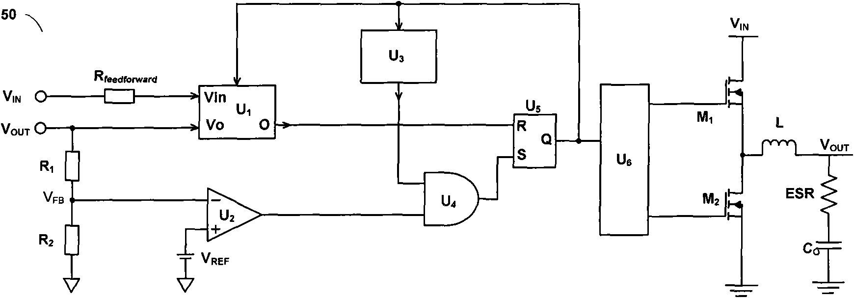
technical field [0001] The present invention relates to direct current conversion circuits, and more particularly, the present invention relates to constant on-time direct current conversion circuits. Background technique [0002] Due to its superior load transient response, simple internal structure and smooth operation mode switching, the constant on-time DC conversion circuit has been well applied in the field of power conversion. [0003] Such as figure 1 The circuit shown is a conventional constant on-time DC conversion circuit 50 . Such as figure 1 As shown, a constant time timer U 1 The input V of the receiving circuit 50 IN and the output of circuit 50 V OUT . The output of circuit 50 V OUT At the same time via the resistor R 1 and resistor R 2 The formed feedback loop obtains a feedback signal V FB , and is sent to the comparator U 2 The inverting input of the comparator U 2 The non-inverting input receives the reference level V REF , whose output is co...

Claims


Application Information

Patent Timeline
Patent Type & Authority Applications(China)
IPC IPC(8): H02M3/00
CPCH02M3/156
Inventor 欧阳茜
Owner CHENGDU MONOLITHIC POWER SYST
Why Eureka
Try Eureka