Multiphase current type PWM rectifier based on dual controllable rectifier bridge of hybrid switch

A hybrid switching, multi-phase current technology, applied in the direction of converting AC power input to DC power output, electrical components, output power conversion devices, etc., can solve problems such as long off time, reducing circuit efficiency, and limiting circuit operating frequency. , to reduce the conduction loss, simplify the drive circuit, and adjust the output voltage

Inactive Publication Date: 2012-01-04
ZHEJIANG UNIV
View PDF1 Cites 0 Cited by
  • Summary
  • Abstract
  • Description
  • Claims
  • Application Information

AI Technical Summary

Problems solved by technology

[0003] The three-phase PWM voltage-type rectifier is a step-up circuit. Under the load requirement that the power supply voltage is lower than the peak value of the grid line voltage, the second-stage DC conversion circuit needs to be connected in series to step down. This not only increases the size and cost of the overall system, and reduces the efficiency of the circuit
The three-phase PWM current source rectifier is a step-down rectifier, and the output voltage of the DC side is lower than the peak value of the grid line voltage; however, the rectifier bridge needs to use IGBT and fast recovery diode in series, because the reverse blocking ability of IGBT is poor, and diodes are needed to bear Back pressure, so the conduction loop increases the conduction loss of two diodes, reducing the efficiency of the circuit; in addition, each IGBT of the lower bridge arm needs an auxiliary power supply to drive, plus the driving power supply of the IGBT of the upper bridge arm, a total of 4-way driving power supply; in addition, the price of high-power IGBT is higher than that of thyristor with the same current and voltage tolerance
[0005] However, although the use of hybrid switches can reduce the cost of switching devices in the circuit, the long turn-off time of the thyristor limits the operating frequency of the circuit
Therefore, in order to suppress the grid-side current harmonics and reduce the ripple of the DC-side current, it is necessary to increase the size and cost of the inductor and capacitor in the filter, so the overall advantage of this circuit is not obvious

Method used


Image

  • Multiphase current type PWM rectifier based on dual controllable rectifier bridge of hybrid switch
  • Multiphase current type PWM rectifier based on dual controllable rectifier bridge of hybrid switch
  • Multiphase current type PWM rectifier based on dual controllable rectifier bridge of hybrid switch

Examples


Embodiment Construction

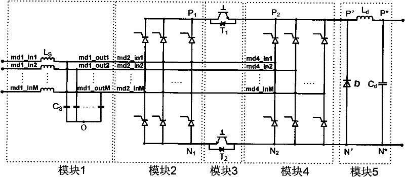
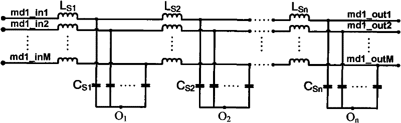
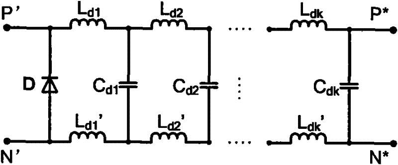
[0044] see figure 1 , the polyphase current type PWM rectifier based on the dual controllable rectifier bridge of hybrid switch of the present invention is made up of five modules, wherein module 1 is made up of M groups of LC filters, and module 2 and module 4 are thyristor M-phase rectifier bridge respectively , module 3 is two independently controlled reverse conduction fully controlled electronic switches T 1 , T 2 , module 5 is an LC filter with a freewheeling diode;

[0045] The input terminals md1_in1, md1_in2, ..., md1_inM of module 1 are respectively connected to the M-phase incoming lines of the power grid, and the output terminals md1_out1, md1_out2, ..., md1_out_M of module 1 are respectively connected to the bridge arms of each phase of module 2 and module 4 Points md2_in1, md2_in2, ..., md2_inM and md4_in1, md4_in2, ..., md4_inM, the ends of the M filter capacitors of module 1 are connected to the midpoint O;

[0046] Module 2 positive output P 1with module 4...


PUM


Abstract

The invention discloses a multiphase current type PWM rectifier based on the dual controllable rectifier bridge of a hybrid switch, which is composed of five modules, wherein the module 1 is composed of an LC filter, the modules 2 and 4 are respectively a thyristor rectifier bridge, the module 3 can be two reverse-conducting full-control electronic switches which are independently controlled, andthe module 5 is an LC filter with a freewheel diode. The rectifier with the structure is mainly characterized in that two groups of thyristor rectifier bridges are adopted so as to provide enough time for the thyristor to conduct and restore to the forward blocking state; and requirements on thyristor cut-off speed by the rectifier bridge can be lowered. Thus, the invention can lower limitation on the working frequency of the rectifier circuit by the cut-off time of the thyristor of a bridge arm in the rectifier bridge, inhibits network side harmonic wave, and reduces the cost of the switching element of the rectifier without increasing the cost of filtering elements.

Description

technical field [0001] The invention relates to a multi-phase current-type PWM rectifier, in particular to a multi-phase current-type PWM rectifier based on a mixed-switch double controllable rectifier bridge, and belongs to the technical field of power electronic power conversion. Background technique [0002] At present, the medium and high-power three-phase PWM rectifiers with limited harmonic content on the grid side mostly use three-phase PWM voltage-type rectifiers or three-phase PWM current-type rectifiers. [0003] The three-phase PWM voltage-type rectifier is a step-up circuit. Under the load requirement that the power supply voltage is lower than the peak value of the grid line voltage, the second-stage DC conversion circuit needs to be connected in series to step down. This not only increases the size and cost of the overall system, Furthermore, the efficiency of the circuit is reduced. The three-phase PWM current source rectifier is a step-down rectifier, and th...

Claims


Application Information

Patent Timeline
Patent Type & Authority Patents(China)
IPC IPC(8): H02M7/162H02M1/12H02M1/14
Inventor 姜礼节吕征宇汪槱生
Owner ZHEJIANG UNIV
Why Eureka
Try Eureka