Switched-tank DC transformer and voltage ratio switching method thereof

a dc transformer and voltage ratio technology, applied in the direction of electric variable regulation, process and machine control, instruments, etc., can solve the problems of low power transformation efficiency, inability to achieve high efficiency of low-frequency switching dc transformers and full-bridge llc circuits, and inability to adjust the output voltage thereof. , to achieve the effect of high power transformation efficiency, adjustable output voltage, and limited output voltage rang

Active Publication Date: 2020-12-29
DELTA ELECTRONICS (SHANGHAI) CO LTD
View PDF18 Cites 4 Cited by
  • Summary
  • Abstract
  • Description
  • Claims
  • Application Information

AI Technical Summary

Benefits of technology

[0006]An object of the present disclosure provides a switched-tank DC transformer and a voltage ratio switching method thereof. In the switched-tank DC transformer, every support capacitor and every resonance tank is switchable to be in a normal state or a voltage ratio switching state. Accordingly, the voltage ratio of the switched-tank DC transformer is changed at will. When the input voltage varies in a wide range, the range of the output voltage can be limited by adjusting the voltage ratio of the switched-tank DC transformer. Therefore, both the high efficiency of power transformation and the adjustable output voltage are achieved. Moreover, with regard to the voltage regulator module including the switched-tank DC transformer, the efficiency and quality of supplying power thereof are enhanced.

Problems solved by technology

However, due to the high voltage ratio of the low-frequency switching DC transformer, the efficiency of power transformation thereof is low.
In addition, due to the fixed voltage ratio of the full-bridge LLC circuit, the output voltage thereof is not adjustable.
Consequently, neither the low-frequency switching DC transformer nor the full-bridge LLC circuit is able to achieve the high efficiency as well as the adjustable output voltage.

Method used


Image

  • Switched-tank DC transformer and voltage ratio switching method thereof
  • Switched-tank DC transformer and voltage ratio switching method thereof
  • Switched-tank DC transformer and voltage ratio switching method thereof

Examples


Embodiment Construction

[0020]The present disclosure will now be described more specifically with reference to the following embodiments. It is to be noted that the following descriptions of preferred embodiments of this disclosure are presented herein for purpose of illustration and description only. It is not intended to be exhaustive or to be limited to the precise form disclosed.

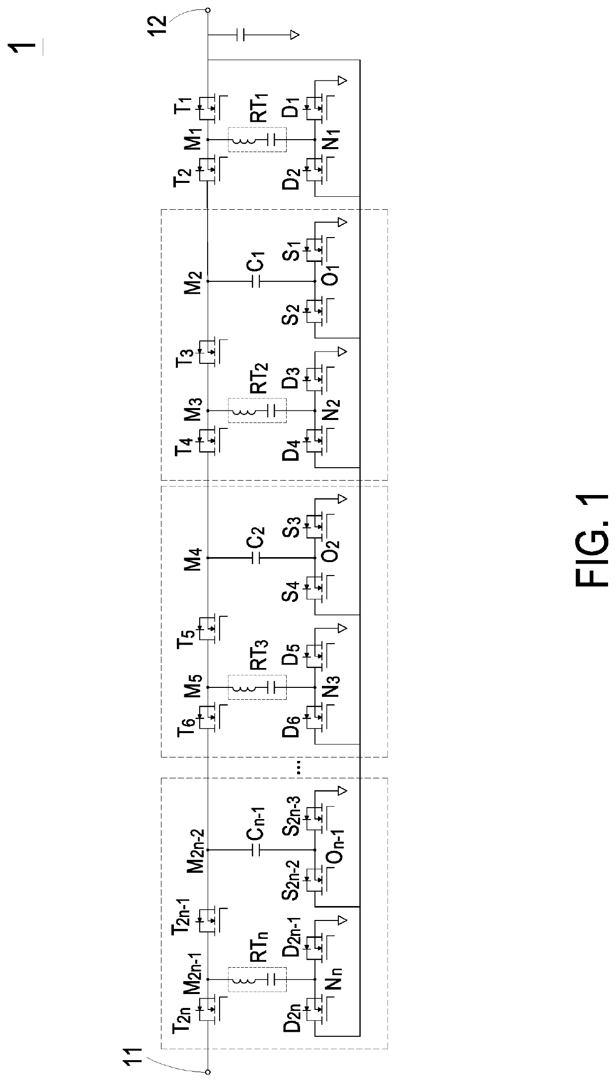
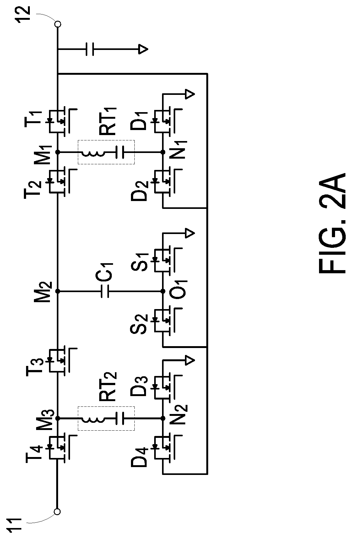
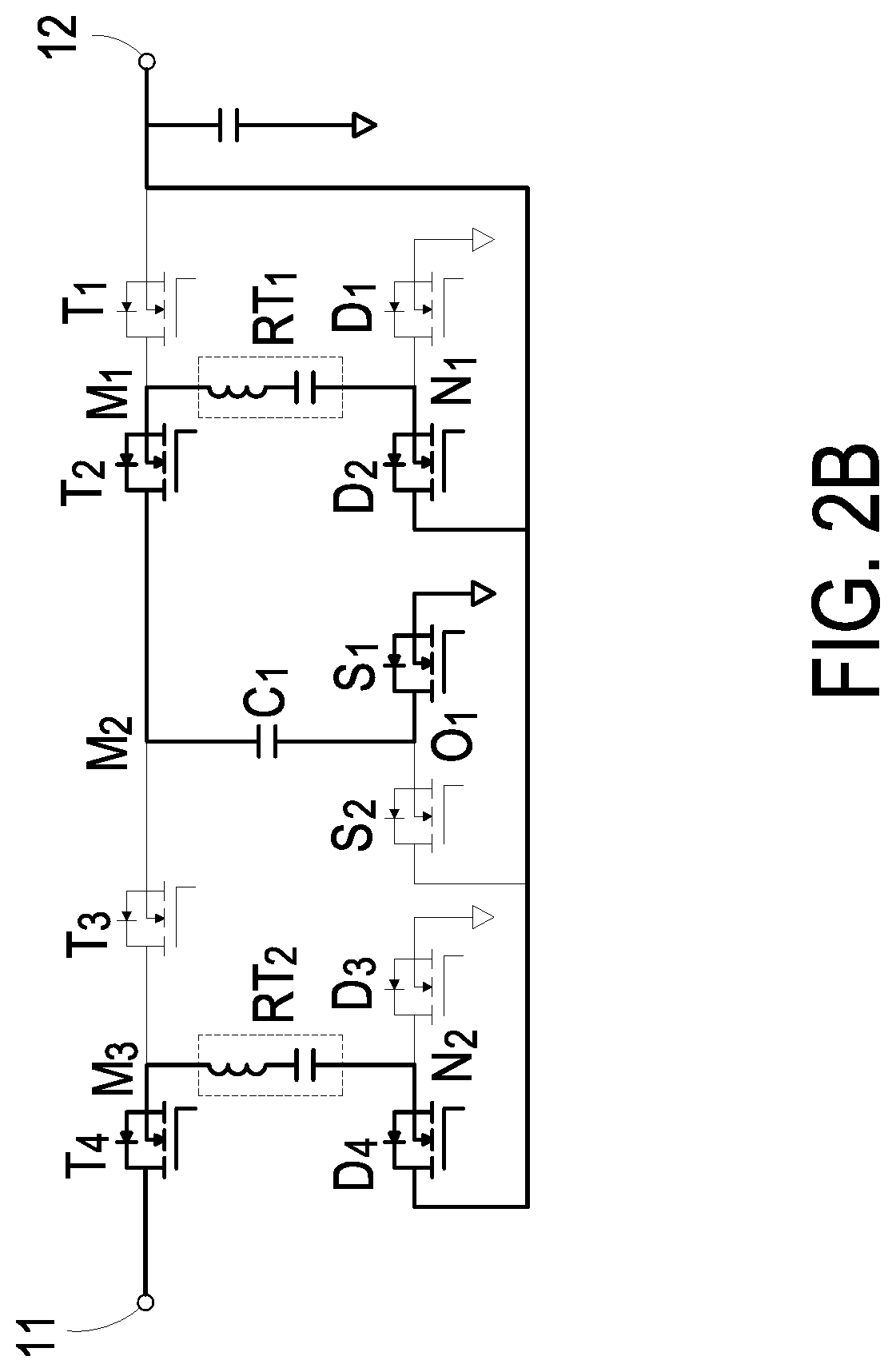
[0021]FIG. 1 is a schematic circuit diagram illustrating a switched-tank DC transformer according to an embodiment of the present disclosure. As shown in FIG. 1, the switched-tank DC transformer 1 includes an input terminal 11, an output terminal 12, 2n inverting switches (T1, T2 to T2n), 2n rectifying switches (D1, D2 to D2n), 2n−2 clamping switches (S1, S2 to S2n−2), n resonance tanks (RT1, RT2 to RTn) and n−1 support capacitors (C1, C2 to Cn-1), where n is an integer larger than or equal to 2. There are an input voltage and an output voltage on the input terminal 11 and the output terminal 12 respectively. The ratio of the i...


PUM


Abstract

A switched-tank DC transformer and a voltage ratio switching method thereof are provided. The switched-tank DC transformer includes an input terminal, an output terminal, 2n inverting switches, 2n rectifying switches, 2n−2 clamping switches, n resonance tanks and n−1 support capacitors. The inverting switches are serially connected in sequence. There is an inverting node between every two neighboring inverting switches. A terminal of the rectifying switch is connected with a rectifying node. A terminal of the two clamping switch is electrically connected with a clamping node. The resonance tank is electrically connected between the inverting node and the rectifying node. The support capacitor is electrically connected between the inverting node and the clamping node. Every support capacitor and every resonance tank is switchable to be in a normal state or a voltage ratio switching state, thus a voltage ratio of the switched-tank DC transformer is allowed to vary correspondingly.

Description

CROSS-REFERENCE TO RELATED APPLICATION[0001]This application claims priority to China Patent Application No. 201811338938.9, filed on Nov. 12, 2018, the entire content of which is incorporated herein by reference for all purposes.FIELD OF THE DISCLOSURE[0002]The present disclosure relates to a switched-tank DC transformer, and more particularly to a switched-tank DC transformer and a voltage ratio switching method thereof.BACKGROUND OF THE DISCLOSURE[0003]For ensuring the performance of the efficiency and quality of supplying power, the voltage regulator module (VRM) with intermediate bus architecture (IBA) is usually utilized for transforming the power. The intermediate bus architecture includes an intermediate bus transformer. Generally, the conventional intermediate bus transformer is a low-frequency switching DC transformer or a full-bridge LLC circuit. The low-frequency switching DC transformer regulates the output voltage by changing the duty ratio, thus the adjustable output ...

Claims


Application Information

Patent Timeline
Patent Type & Authority Patents(United States)
IPC IPC(8): H02M3/335H02M3/337H02M1/00H02M3/07
CPCH02M3/33569H02M3/33546H02M2001/0058H02M3/3376H02M3/073H02M3/07H02M3/33523H02M3/33576H02M3/28H02M1/007H02M3/01H02M3/33571Y02B70/10H02M1/0058
Inventor LI, MINGYE, YIQING
Owner DELTA ELECTRONICS (SHANGHAI) CO LTD
Why Eureka
Try Eureka