Welding trolley with bidirectional locking mechanism

A locking mechanism, welding trolley technology, applied in welding equipment, auxiliary welding equipment, welding/cutting auxiliary equipment, etc., to achieve the effect of compact coordination, easy use, maintenance and repair, compact and concise structure

Inactive Publication Date: 2010-07-28
BEIJING INSTITUTE OF PETROCHEMICAL TECHNOLOGY
View PDF5 Cites 9 Cited by
  • Summary
  • Abstract
  • Description
  • Claims
  • Application Information

AI Technical Summary

Problems solved by technology

At present, there are few domestic pipeline all-position welding trolleys that combine the two well and are easy to install.

Method used


Image

  • Welding trolley with bidirectional locking mechanism
  • Welding trolley with bidirectional locking mechanism
  • Welding trolley with bidirectional locking mechanism

Examples


Embodiment Construction

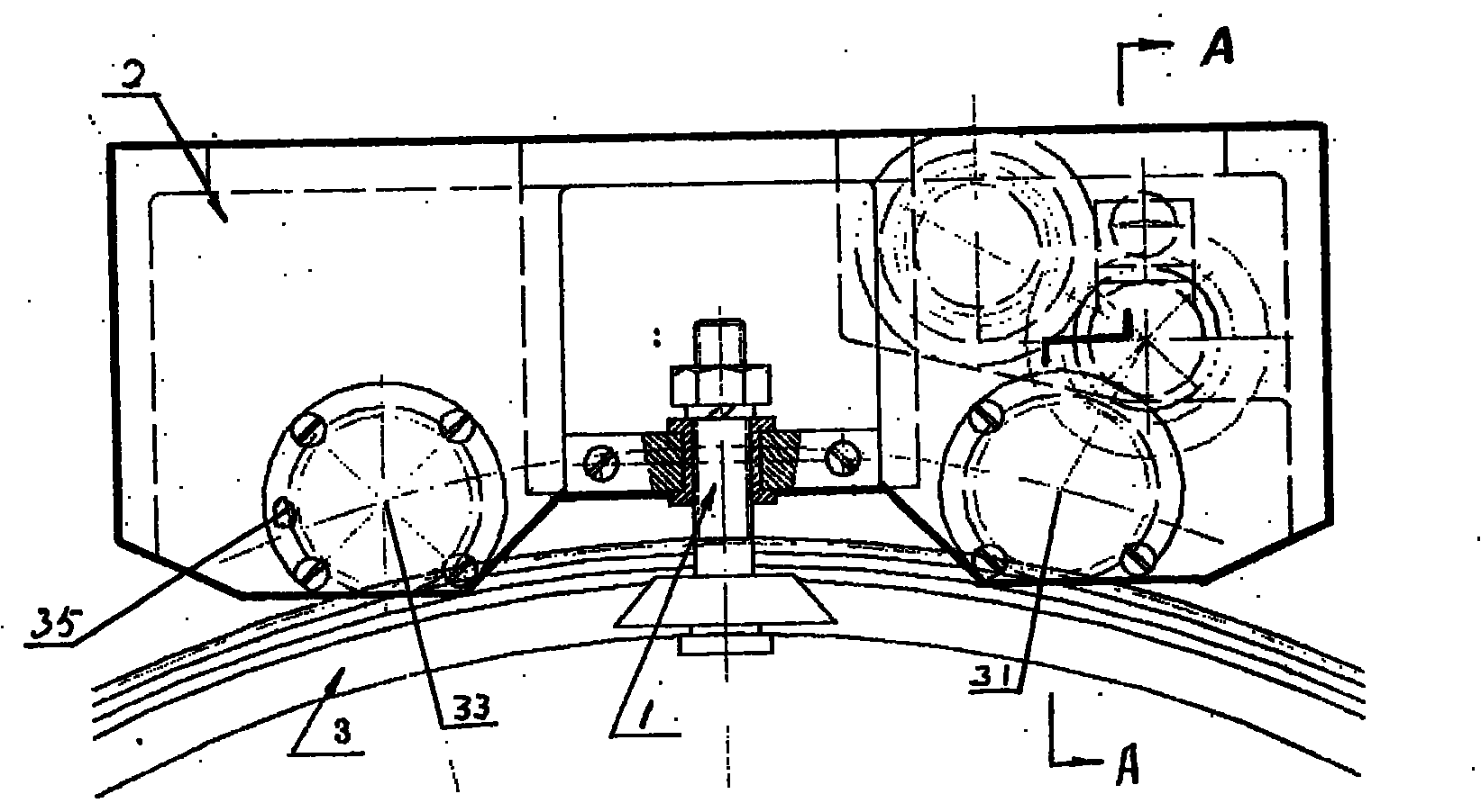
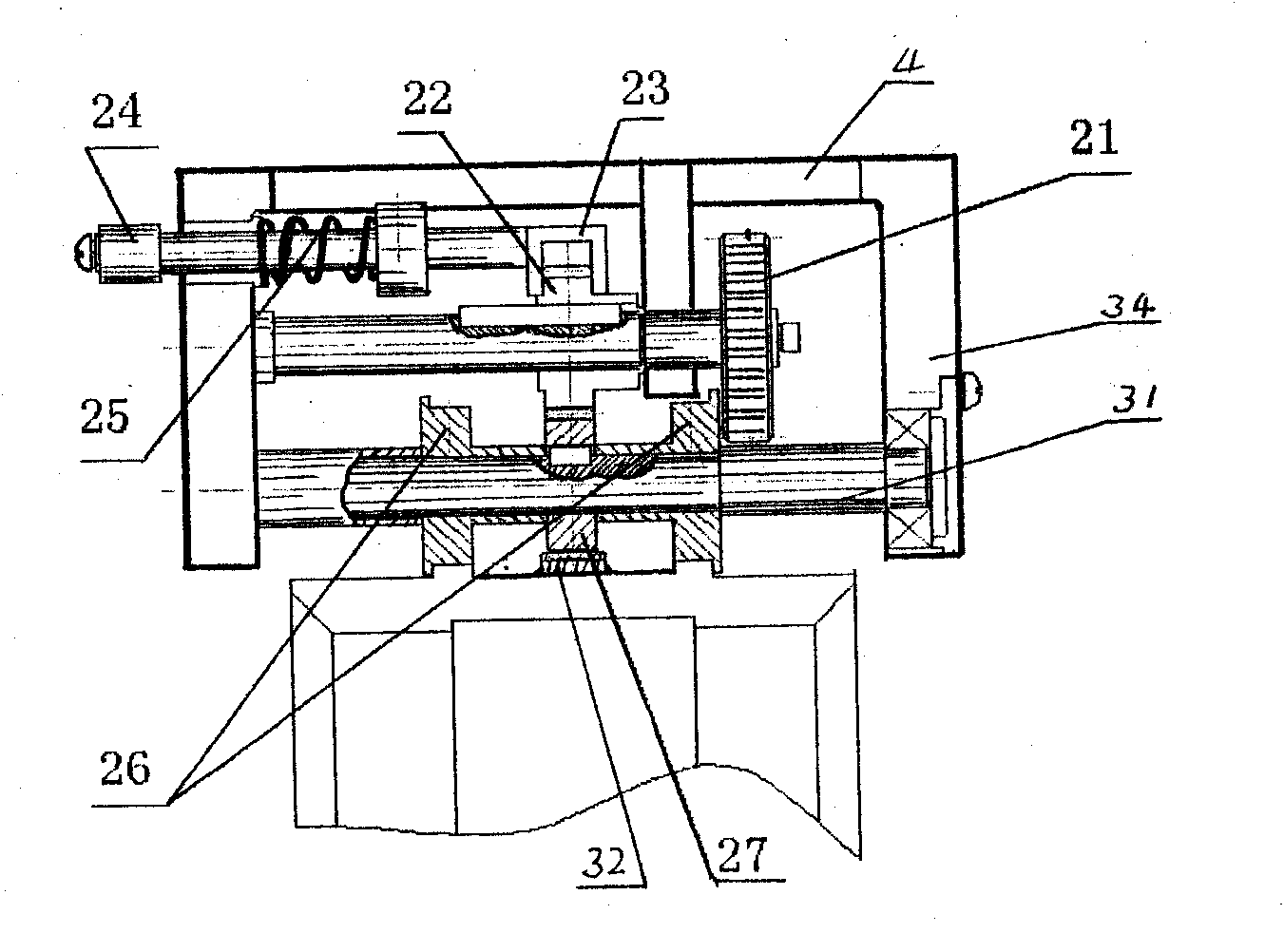
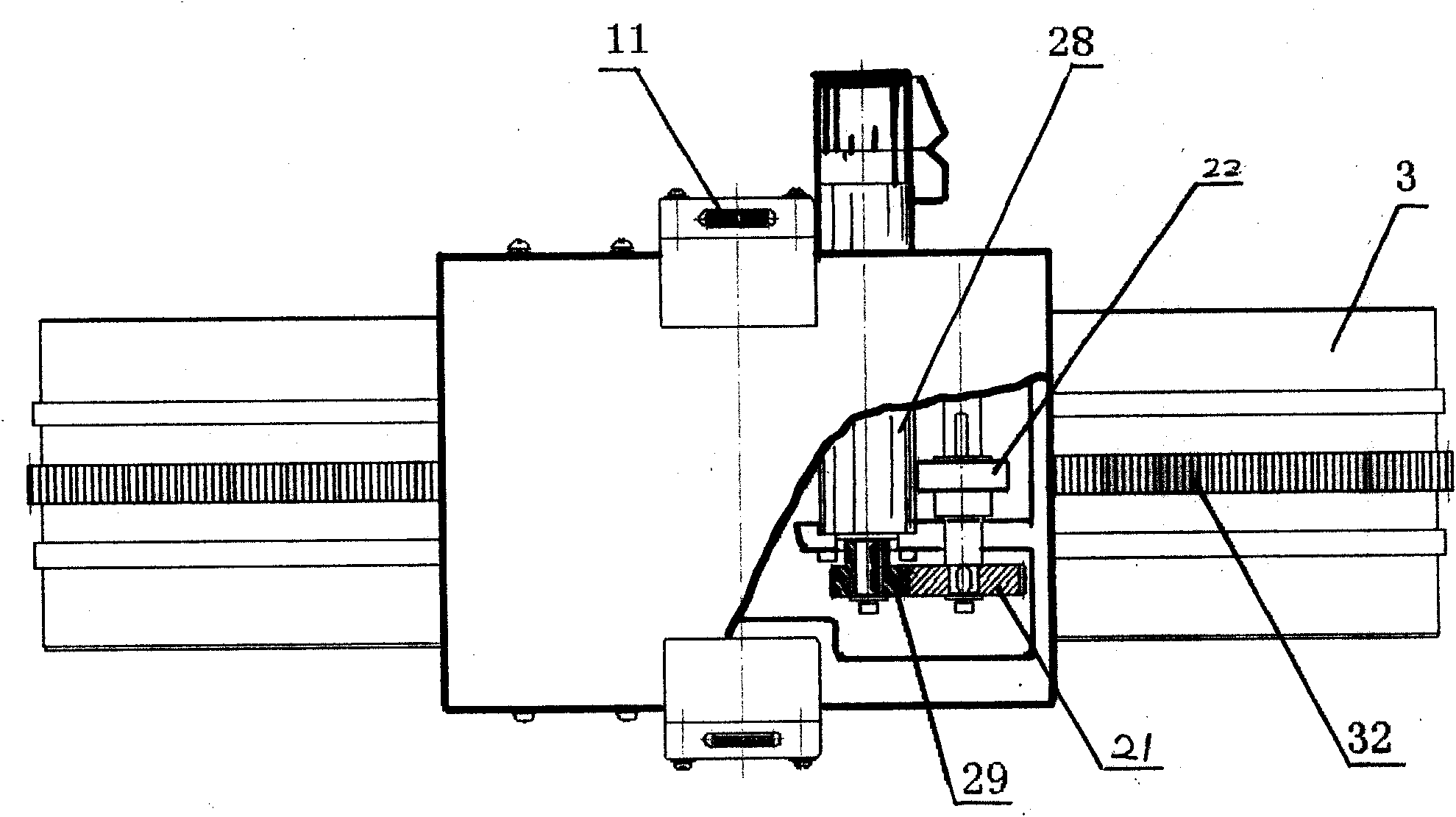
[0014] Depend on Figure 1 to Figure 5 As shown, a welding trolley with a two-way locking mechanism is mainly composed of a trolley locking mechanism 1 and a trolley traveling mechanism 2, wherein: a motor 28 with a reducer is connected with a motor shaft gear 29 through a key, and the motor shaft The gear 29 is meshed with the intermediate wheel A21, and the other side of the axis where the intermediate wheel A21 is located is connected to the intermediate wheel B22 with a long key, and the intermediate wheel B22 is meshed with the transmission gear 27 at the center of the front drive shaft 31, and the transmission gear 27 is finally welded to the The guide rack 32 in the center of the guide rail 3 is engaged, and a front drive wheel 26 is respectively installed on the left and right sides of the front drive shaft 31, so that the rotation of the motor 28 is converted into the rotation of a pair of front drive rollers 26, and the rear drive shaft 33 both sides Also each is ins...


PUM


Abstract

The invention discloses a welding mechanism with a bidirectional locking mechanism, mainly comprising a trolley locking mechanism (1) and a trolley walking mechanism (2), wherein a motor shaft gear (29) in the trolley walking mechanism (2) is mutually meshed with an intermediate gear (21); an intermediate gear B (22) is meshed with a driving gear (27) which is meshed with a guide rack (32); front driving wheels (26) are respectively arranged on the left side and the right side of a front driving shaft (31) and rear driven wheels (35) are respectively arranged on the left side and the right side of a rear driving shaft (33), thereby forming a main body of the trolley walking mechanism (2); a compression shaft (14), a cone-shaped compression wheel (15), a sliding block (12), a stop block (10) and a locking wheel (11) form the locking mechanism (1); and the compression of the compression wheel (15) on the side of a guide rail (3) can be realized by rotating the compression shaft (14) and the locking wheel (11). The invention has the advantages of simple structure, smallness, flexibility, reliable work, low construction cost and simple and easy maintenance and repairing.

Description

technical field [0001] The invention relates to a structure of a welding trolley, in particular to a track all-position welding trolley equipped with a bidirectional locking mechanism. Background technique [0002] The guide rail all-position welding robot is a type of welding robot that performs welding operations along the guide rail. Its running track is relatively fixed and its movement repeatability is good. It is suitable for welding regular welds. The welding trolley is the driving mechanism to realize the automatic welding process. It is installed on the welding guide rail and moves along the pipe wall with the welding torch. It is one of the important links to realize the automatic welding of the groove. The all-position welding of the pipeline requires the welding trolley to move along the circular weld seam for a whole circle, and the welding trolley crawls smoothly on the pipe along the guide rails to obtain high-quality weld seams. In order to achieve smooth cr...

Claims


Application Information

Patent Timeline
Patent Type & Authority Applications(China)
IPC IPC(8): B23K37/00
Inventor 薛龙张卫义曹俊芳梁亚军邹勇曹莹瑜
Owner BEIJING INSTITUTE OF PETROCHEMICAL TECHNOLOGY
Why Eureka
Try Eureka