Impeller drive control mechanism of stationary crude oil washing machine

A technology of drive control and tank washing machine, which is applied in the direction of cleaning equipment for motor vehicles, oil tankers, and ship liquid tanks, etc. Main drive worm gear ratio and other issues

Active Publication Date: 2011-12-28
HAIYING ENTERPRISE GROUP
View PDF1 Cites 0 Cited by
  • Summary
  • Abstract
  • Description
  • Claims
  • Application Information

AI Technical Summary

Problems solved by technology

However, in the current tank washing machine, the impeller is driven by the high-pressure liquid flow, and its speed changes with the change of pressure. If the liquid flow pressure is unstable, it will cause uneven impeller speed. The transmission ratio between the impeller and the main drive worm cannot be changed by a single machine. In addition, the horizontal speed of the nozzle of the general tank washing machine cannot be adjusted, and the single machine cannot automatically stop the tank washing operation, which affects the implementation and cleaning of various tank washing processes. energy consumption and effect

Method used


Image

  • Impeller drive control mechanism of stationary crude oil washing machine
  • Impeller drive control mechanism of stationary crude oil washing machine
  • Impeller drive control mechanism of stationary crude oil washing machine

Examples


Embodiment Construction

[0014] The present invention will be further described below in conjunction with accompanying drawing.

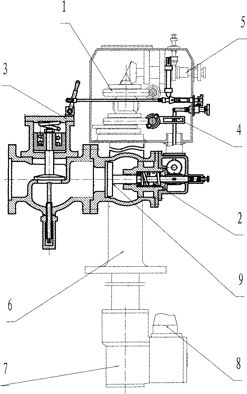
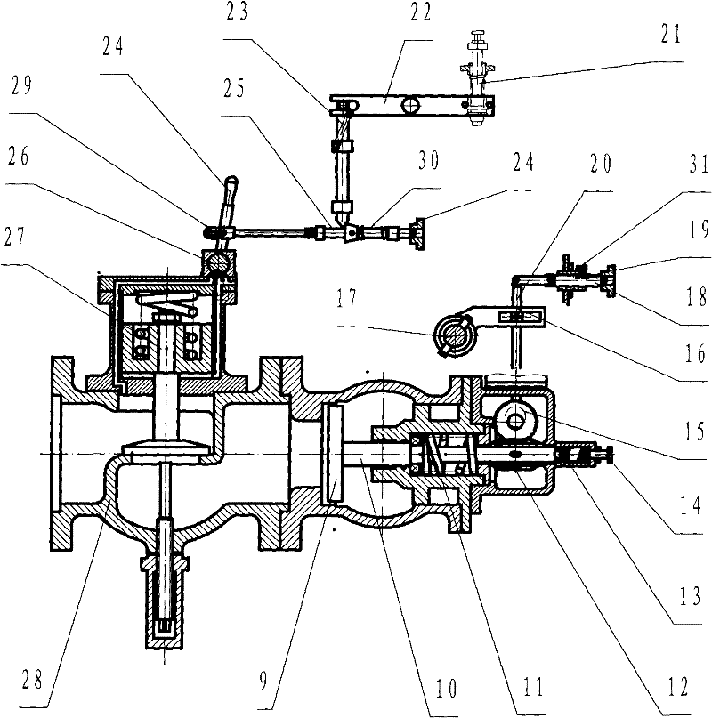
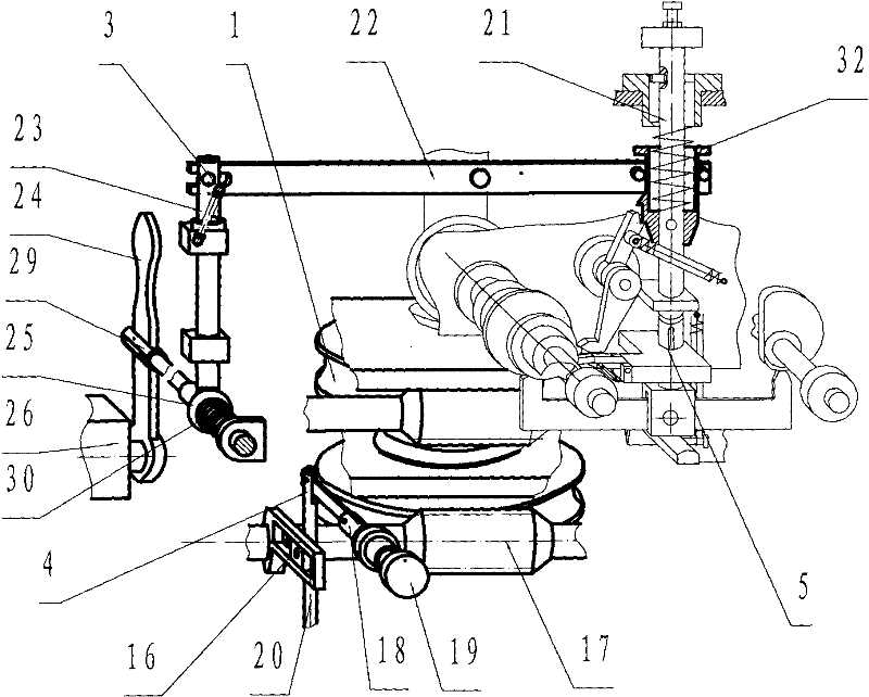
[0015] An impeller drive control mechanism of a stationary crude oil washing machine, including a main transmission part 1 arranged in the body, an impeller drive part 2, an impeller drive start and stop control part 3, and a nozzle horizontal speed adjustment mechanism connected to the impeller drive part 2 4. The impeller driving part 2 includes the impeller 9, the hydraulic control shut-off valve 28 at the front end of the impeller 9, the transmission shaft 10 connected to the rear end of the impeller 9, the main spring 11, the auxiliary spring 13 and the worm 12 set on the transmission shaft 10, and the worm 12 passes through The worm gear 15 meshed with it is connected with the nozzle horizontal rotation speed regulating mechanism 4 .

[0016] Described nozzle horizontal rotational speed regulating mechanism 4 comprises the eccentric wheel on the worm wheel 15, transmi...


PUM


Abstract

The invention discloses an impeller driving control mechanism of a fixed crude oil tank washing machine, which comprises a main transmission part arranged in a body, an impeller driving part, an impeller driving start and stop control part and a nozzle horizontal rotational speed adjustment mechanism connected with the impeller driving part The driving parts of the impeller include the impeller, the hydraulic control shut-off valve at the front end of the impeller, the transmission shaft connected to the rear end of the impeller, the main spring on the transmission shaft, the auxiliary spring and the worm. The mechanism can automatically adjust the axial position of the impeller, and the horizontal speed of the nozzle can be adjusted to realize the automatic shutdown of a single machine.

Description

technical field [0001] The invention relates to an oil tank cleaning device which uses crude oil or seawater as the medium for various oil tanker oil tanks in the shipbuilding industry. Background technique [0002] The main engine of the fixed crude oil washing machine is installed on the hatch cover, and its nozzle part extends into the oil tank. The spiral impeller rotates at a high speed driven by the high-speed fluid. Through multi-stage deceleration transmission, one path is transmitted to the horizontal rotating worm wheel to realize the horizontal 360° rotation of the nozzle seat, and the other path is transmitted to the nozzle to rotate the worm wheel vertically to realize the vertical direction of the nozzle head. Rotation, so that the nozzle head will move according to the spatial spiral curve track during tank cleaning, ensuring the cleaning of the entire inner wall of the oil tank. However, in the current tank washing machine, the impeller is driven by the high...

Claims


Application Information

Patent Timeline
Patent Type & Authority Patents(China)
IPC IPC(8): B63B57/02
Inventor 华福昌王克鹏吴坚
Owner HAIYING ENTERPRISE GROUP
Why Eureka
Try Eureka