Hardening method and hardening device

A technology of quenching device and shaft, applied in the direction of quenching device, coil device, electric heating device, etc., can solve the problem of complex workpiece and achieve good quenching effect

Active Publication Date: 2010-07-28
FUJI ELECTRONICS IND
View PDF6 Cites 5 Cited by
  • Summary
  • Abstract
  • Description
  • Claims
  • Application Information

AI Technical Summary

Problems solved by technology

[0003] Just like the component 51 of the combined crankshaft 50, the structure where the portion protruding from

Method used


Image

  • Hardening method and hardening device
  • Hardening method and hardening device
  • Hardening method and hardening device

Examples


Embodiment Construction

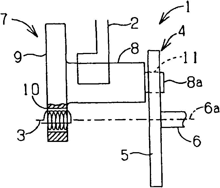
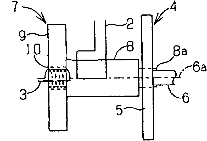
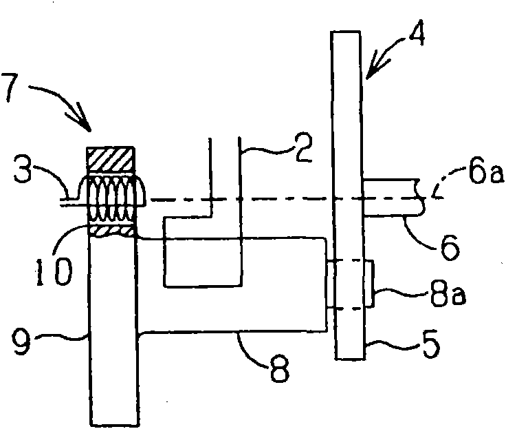
[0059] As shown in FIG. 1( a ), the workpiece 7 to be quenched by the quenching device 1 is composed of a flat plate portion 9 and a shaft portion 8 . The flat plate portion 9 is disc-shaped, and the shaft portion 8 is provided at the center thereof. That is, the shaft portion 8 stands upright on the central portion of the flat plate portion 9 .

[0060] In addition, a hole 10 is provided in the flat plate portion 9 , and the hole 10 is close to the shaft portion 8 . That is, the center of the flat plate portion 9 does not coincide with the center of the hole 10 , and the hole 10 is provided at a position away from the center of the disc-shaped flat plate portion 9 .

[0061] The workpiece 7 having such a shape is used, for example, as a component (component 51 ) of the composite crankshaft 50 shown in FIG. 13( a ). The workpiece 7 is quenched with the quenching device 1 .

[0062] Next, first, the structure of the quenching device 1 will be described, and then the operatio...


PUM


Abstract

An object of the present invention is to provide a hardening method and a hardening device capable of successfully hardening a shaft and an inner wall of a hole of a work in which the hole is formed close to the shaft on a flat plate. A hardening device for hardening a shaft and an inner wall of a hole, the shaft 8 extending vertically from a flat plate 9 and the hole 10 being formed adjacent to the shaft 8, includes a first heating coil 2 that is a conductive body facing the shaft 8 and a second heating coil 3 that is a helical conductive body having at least a portion inserted into the hole, so that the first heating coil 2 and the second heating coil 3 heat the shaft 8 and the inner wall of the hole 10 respectively and simultaneously.

Description

technical field [0001] The present invention relates to a quenching method and a quenching device for a component having a shaft portion and a hole on a flat plate. Background technique [0002] Conventionally, combined crankshafts were assembled after quenching each component. Here, the combined crankshaft is a crankshaft having a structure shown in FIG. 13( a ) and FIG. 13( b ). That is, as shown in FIG. 13( a ), a part 51 as one of the constituent elements of the combined crankshaft 50 has a structure in which a shaft 54 ​​(shaft portion) is integrally formed at the center of a flat plate 53 (circular plate). In addition, a hole 55 is provided in the flat plate 53 , and the hole 55 is close to the shaft portion 54 . In addition, as shown in FIG. 13( b ), a pin 52 as another component is fixed in the hole 55 by means of a close fit or the like. In addition, the flat plates 53 of the two parts 51 are connected by a common pin 52 to constitute the combined crankshaft 50 ....

Claims


Application Information

Patent Timeline
IPC IPC(8): C21D1/10C21D9/30C21D1/62
CPCH05B6/102C21D9/08H05B6/06H05B6/44Y02P10/25
Inventor 巳之上润二渡边弘子小山雅行宫下英夫
Owner FUJI ELECTRONICS IND
Why Eureka
Try Eureka