Al technical title is built by PatSnap Al team. It summarizes the technical point description of the patent document.
A technology for metal heat treatment and quenching equipment, applied in heat treatment equipment, heat treatment furnaces, quenching devices, etc., can solve the problems of low work efficiency and inconvenient transportation of mobile coolant in large quantities, and achieve the effect of improving work efficiency
Inactive Publication Date: 2020-07-31
南通祥博热处理科技有限公司
View PDF0 Cites 1 Cited by
Summary
Abstract
Description
Claims
Application Information
AI Technical Summary
This helps you quickly interpret patents by identifying the three key elements:
Problems solved by technology
Method used
Benefits of technology
Problems solved by technology
[0003] In actual use, it is not convenient to transport and move a large amount of metals to the cooling liquid after heating. If the metals are moved one by one, the work efficiency will be low.
Method used
Image
Click on the blue label to locate the original text in one second.
Reading with bidirectional positioning of images and text.
Examples
Embodiment Construction
[0025] In order to make the object, technical solution and advantages of the present invention clearer, the present invention will be further described in detail below in combination with specific embodiments and with reference to the accompanying drawings. It should be understood that these descriptions are exemplary only, and are not intended to limit the scope of the present invention. Also, in the following description, descriptions of well-known structures and techniques are omitted to avoid unnecessarily obscuring the concept of the present invention.
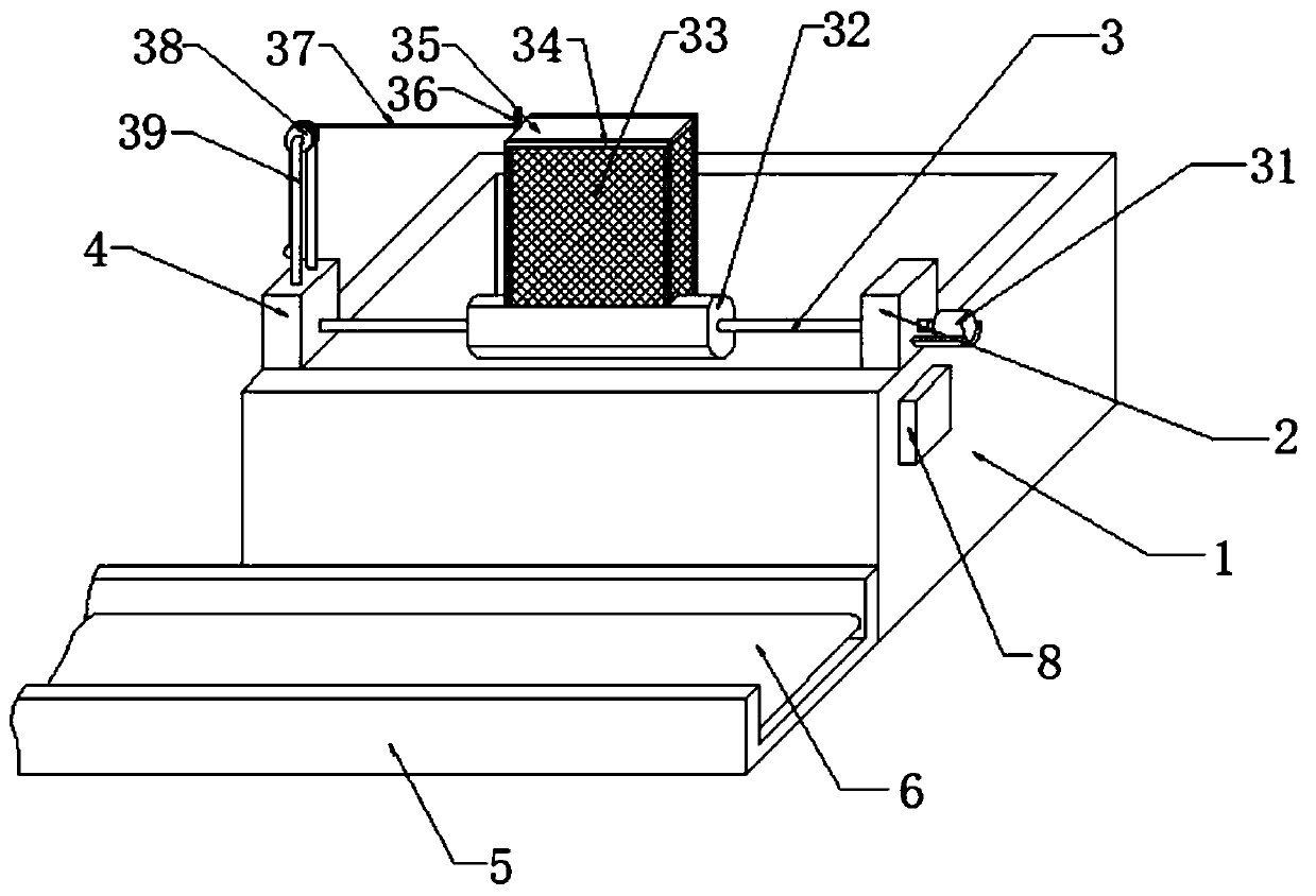
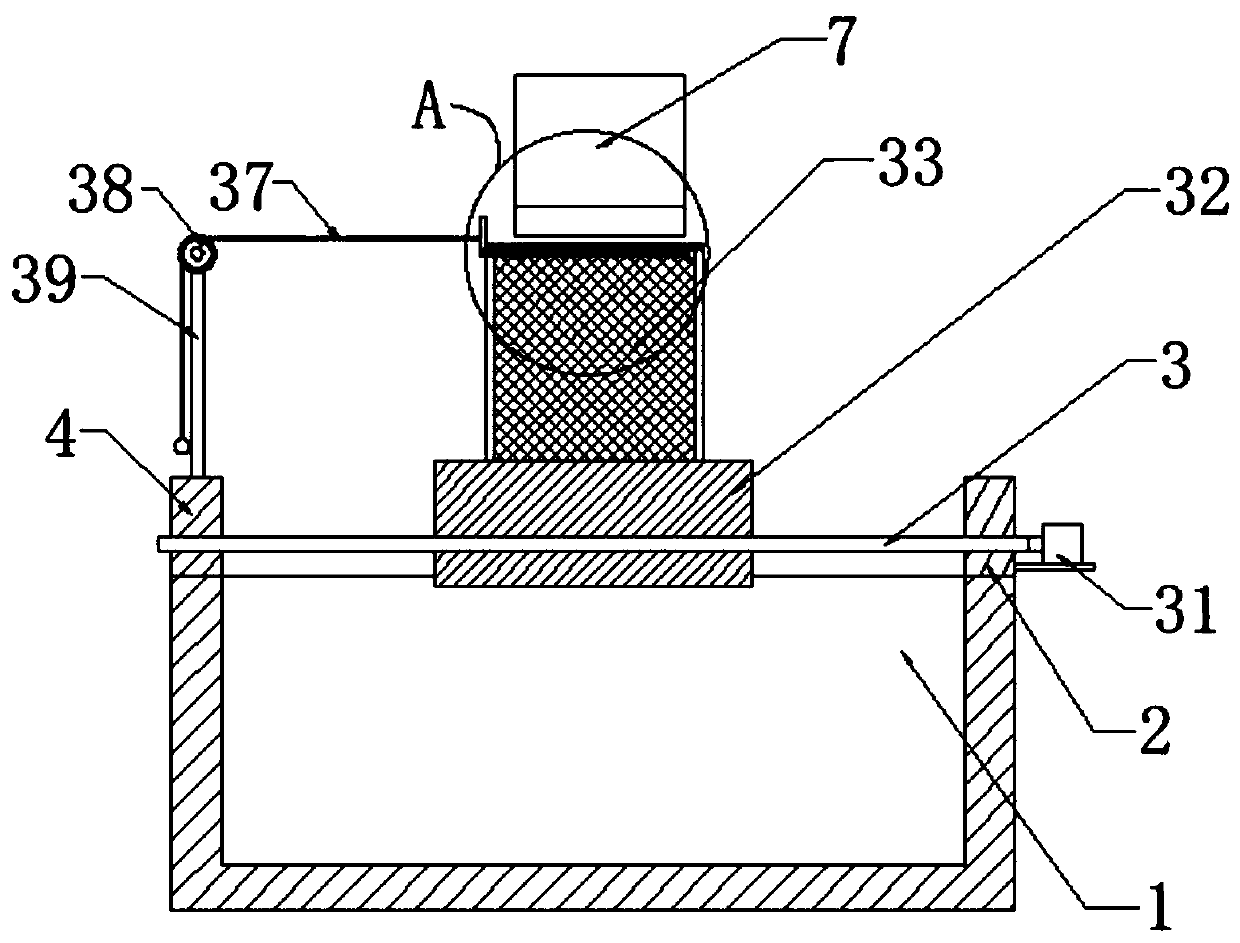
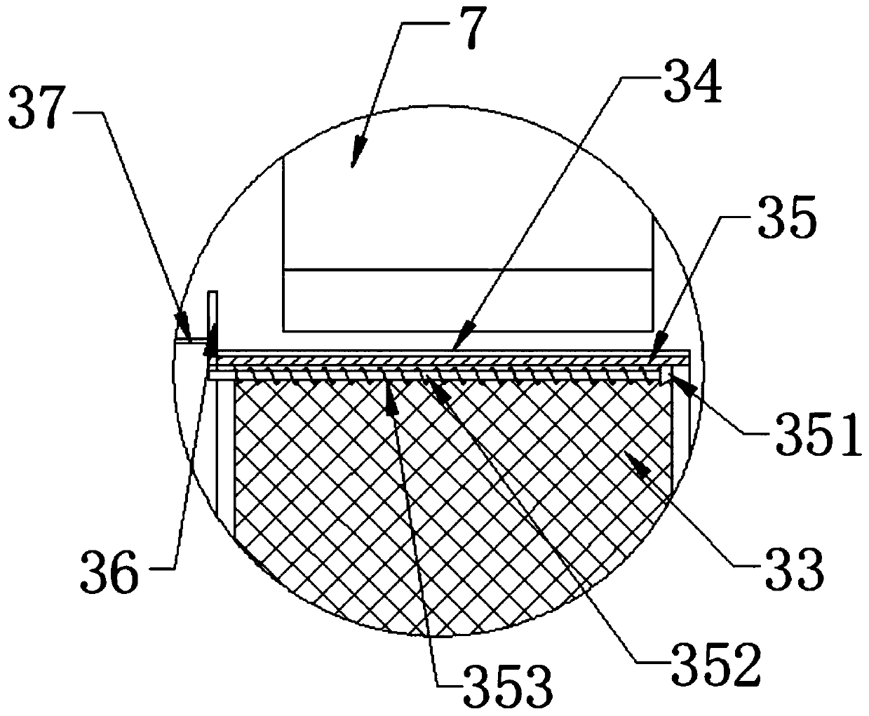
[0026] like Figure 1-5 As shown, a kind of metal quenching equipment for metal heat treatment proposed by the present invention includes a coolant tank 1, a first support platform 2, a rotating shaft 3, a second support platform 4, a drum 32, a mesh box 33, an installation frame 34, and a sealing plate 35, convex strip 36, stay cord 37, guide pulley 38 and round bar 39;
[0027] The corner position on one side of the u...
PUM
Abstract
Disclosed is a metal quenching device for metal heat treatment. The metal quenching device for metal heat treatment comprises a cooling liquid tank, a first supporting table, a rotating shaft, a second supporting table, a roller, a mesh box, a mounting frame, a sealing plate, a protruding bar, a pull rope, a guide pulley and a round rod; the first supporting table is fixed to the corner of one side of the upper surface of the cooling liquid tank; the second supporting table is fixed to the side, away from the first supporting table, of the upper side face of the cooling liquid tank; the two ends of the rotating shaft are installed at the upper ends of the first supporting table and the second supporting table in a penetrating manner respectively; the middle of the rotating shaft is sleevedwith the roller, and the mesh box is fixed to the annular side face of the roller; the mounting frame is fixed to the end, away from the roller, of the mesh box, and the sealing plate is mounted in the mounting frame; the protruding bar is fixed to the middle of the side, close to the second supporting table, of the outer surface of the sealing plate, and the side, close to the first supporting table, of the outer surface of the protruding bar is connected with the pull rope; and the end, away from the protruding bar, of the pull rope is wound around the guide pulley, and the guide pulley sleeves the upper end of the round rod. The metal quenching device for metal heat treatment facilitates the one-time mass movement of small-size metal in the quenching process and effectively improves the working efficiency.
Description
technical field [0001] The invention relates to the field of metal heat treatment equipment, in particular to metal quenching equipment for metal heat treatment. Background technique [0002] Heat treatment refers to a metal thermal processing process in which materials are heated, kept warm and cooled in a solid state to obtain the desired structure and properties. Quenching is an important part of the heat treatment process. Quenching is to heat the steel above the critical temperature, hold it for a certain period of time, and then cool it at a rate greater than the critical cooling rate, so as to obtain an unbalanced structure mainly composed of martensite (and also obtain bainite or maintain single-phase austenite according to needs). ) of a heat treatment process. Quenching is the most widely used process method in steel heat treatment process. The most common ones are water-cooled quenching, oil-cooled quenching, air-cooled quenching, etc. [0003] In actual use, i...
Claims
Application Information
Patent Timeline
Application Date:The date an application was filed.
Publication Date:The date a patent or application was officially published.
First Publication Date:The earliest publication date of a patent with the same application number.
Issue Date:Publication date of the patent grant document.
PCT Entry Date:The Entry date of PCT National Phase.
Estimated Expiry Date:The statutory expiry date of a patent right according to the Patent Law, and it is the longest term of protection that the patent right can achieve without the termination of the patent right due to other reasons(Term extension factor has been taken into account ).
Invalid Date:Actual expiry date is based on effective date or publication date of legal transaction data of invalid patent.