Camshaft high-frequency quenching device capable of effectively absorbing and removing water vapor

A high-frequency quenching and camshaft technology, applied in the direction of quenching device, improving process efficiency, improving energy efficiency, etc., can solve problems such as affecting the observation or operation of the quenching device, unfavorable normal operation of the quenching device, high humidity, etc. Adsorption range, easy collection, avoid the effect of excessive humidity

Pending Publication Date: 2022-06-21
熊建
View PDF0 Cites 1 Cited by
  • Summary
  • Abstract
  • Description
  • Claims
  • Application Information

AI Technical Summary

Problems solved by technology

[0003] At present, in the process of repairing the camshaft, high-frequency quenching is required for the camshaft. High-frequency quenching is mainly used for surface quenching of industrial metal parts. During the process of high-frequency quenching, a high-frequency induction current will be formed on the surface of the workpiece. The surface or part of the part is heated rapidly, and after a few seconds, the quenching work is completed by spraying water immediately, but in the process of high-frequency quenching, a large amount of

Method used


Image

  • Camshaft high-frequency quenching device capable of effectively absorbing and removing water vapor
  • Camshaft high-frequency quenching device capable of effectively absorbing and removing water vapor
  • Camshaft high-frequency quenching device capable of effectively absorbing and removing water vapor

Examples


Embodiment 1

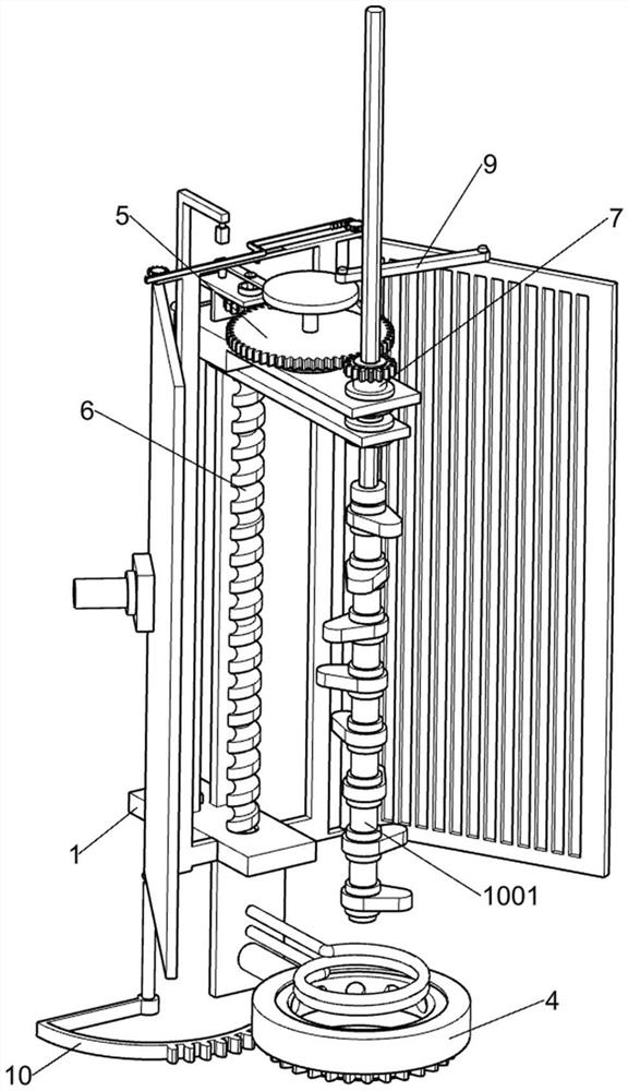
[0036] A camshaft high-frequency quenching device that can effectively absorb water vapor, such as figure 1 , figure 2 , image 3 , Figure 4 , Figure 5 and Image 6 As shown, it includes a slotted guide plate frame 1, a vertical plate 2, an induction heating hollow copper tube 3, a heat dissipation part 4, a driving part 5, a conveying part 6, a rotating part 7 and an adsorption part 8, and the slotted guide plate frame 1 A vertical plate 2 is fixed on the bottom, an induction heating hollow copper tube 3 is fixed on the front side of the vertical plate 2, and a heat dissipation part 4 is arranged on the vertical plate 2, and the heat dissipation part 4 is used for the camshaft 1001 during the quenching process. For cooling, the slotted guide plate frame 1 is provided with a driving member 5, the slotted guide plate frame 1 is provided with a conveying member 6, and the conveying member 6 is used to intermittently transport the camshaft 1001 downward, and the slotted gu...

Embodiment 2

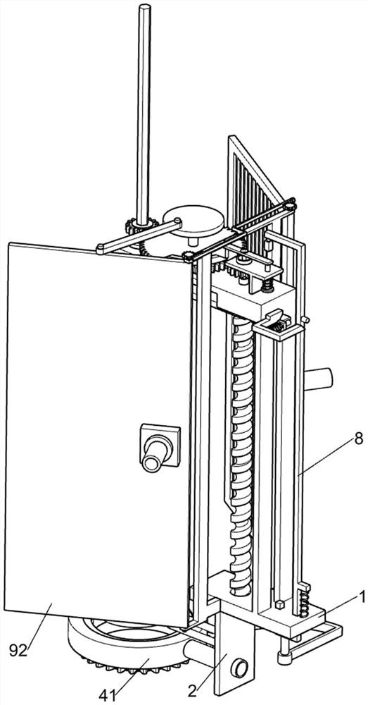
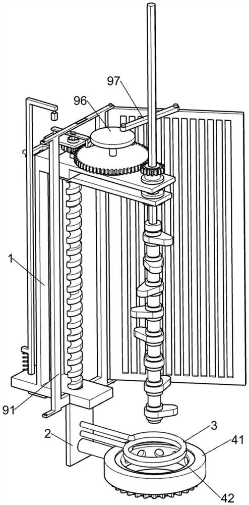
[0045] On the basis of Example 1, as Figure 7 As shown, it also includes a water vapor absorbing member 9, which is arranged on the slotted guide plate frame 1 and connected with the drive shaft 52. For water vapor suction, the water vapor suction part 9 includes a fixed frame 91, a swing adsorption plate 92, a conveying pipe 93, a rotating gear 94, a Z-shaped rack 95, a rotating disk 96 and a connecting rod 97, and the slotted guide plate frame 1 A fixed frame 91 is fixedly connected to the lower part, and two swing adsorption plates 92 are rotatably connected to the fixed frame 91. The swing adsorption plates 92 are symmetrically arranged, and the two swing adsorption plates 92 will swing synchronously. The swing adsorption plate 92 is used for adsorption and quenching process. The water vapor generated around the middle camshaft 1001 avoids excessive humidity in the air. The outer side of the swing adsorption plate 92 is fixed with a conveying pipe 93, which is connected t...

Embodiment 3

[0048] On the basis of Example 2, as Figure 8 As shown, the spraying angle adjustment part 10 is also included. The spraying angle adjustment part 10 is arranged on the swing adsorption plate 92 on the left and is connected with the opening rotating ring 42. The spraying angle adjusting part 10 is convenient for adjusting the opening of the opening rotating ring 42. The water spraying position ensures that the surface of the camshaft 1001 can be fully contacted with water. The spraying angle adjustment component 10 includes a gear ring 101, a transmission shaft 102 and an arc-shaped rack 103. The bottom of the open-hole rotating ring 42 is welded with a gear ring 101. The bottom of the swing adsorption plate 92 on the left is fixedly connected with a transmission shaft 102 , the lower part of the transmission shaft 102 is connected with an arc-shaped rack 103 by welding, and the arc-shaped rack 103 meshes with the ring gear 101 .

[0049] During the reciprocating swing of the...


PUM


Abstract

The invention relates to the technical field of camshaft repair, in particular to a camshaft high-frequency quenching device capable of effectively absorbing and removing water vapor, which comprises a slotted guide plate frame, a vertical plate, an induction heating hollow copper pipe, a heat dissipation part and the like, a vertical plate is fixedly connected to the bottom of the grooving guide plate frame, an induction heating hollow copper pipe is fixedly connected to the front side of the vertical plate, and a heat dissipation component is arranged on the vertical plate. Through cooperation of internal parts of the device, the conveying part can intermittently convey the cam shaft downwards, the high-frequency quenching process of the whole cam shaft can be conveniently completed, after quenching is completed, the conveying part can rapidly convey the cam shaft upwards to reset, the next cam shaft can be conveniently quenched, and the production efficiency is improved. Water vapor around the camshaft in the quenching process is adsorbed by swinging the adsorption plate, so that the humidity in the air can be prevented from being too high, a large amount of water vapor can be prevented from being attached to the surfaces of other parts of the device, and normal operation of the device is guaranteed.

Description

technical field [0001] The invention relates to the technical field of camshaft repair, in particular to a high-frequency quenching device for camshafts that can effectively absorb water vapor. Background technique [0002] The camshaft is usually forged from high-quality carbon steel or alloy steel. The camshaft plays the role of controlling the opening and closing of the valve in the piston engine, and it occupies a very important position in the engine. During the use of the camshaft, due to the influence of various factors, the camshaft may have some faults. The faulty camshaft can be used twice after being repaired. Therefore, the faulty camshaft needs to be repaired. [0003] At present, in the process of repairing the camshaft, it is necessary to perform high-frequency quenching on the camshaft. High-frequency quenching is mainly used for surface quenching of industrial metal parts. In the process of high-frequency quenching, the surface of the workpiece will form hig...

Claims


Application Information

Patent Timeline
IPC IPC(8): C21D1/667C21D1/10C21D9/30B01D53/06B01D53/26
CPCC21D1/667C21D1/10C21D9/0062C21D9/30B01D53/06B01D53/261Y02P10/25
Inventor 熊建
Owner 熊建
Why Eureka
Try Eureka