Optimal design method for valve cam profile

A technology of optimized design and gas distribution cam, which is applied in calculation, special data processing applications, instruments, etc., and can solve problems such as flying off

Inactive Publication Date: 2010-07-28
BEIJING INSTITUTE OF TECHNOLOGYGY
View PDF0 Cites 8 Cited by
  • Summary
  • Abstract
  • Description
  • Claims
  • Application Information

AI Technical Summary

Problems solved by technology

If the speed from positive acceleration to negative acceleration is too fast, it is easy to cause flying off phenomenon

Method used


Image

  • Optimal design method for valve cam profile
  • Optimal design method for valve cam profile
  • Optimal design method for valve cam profile

Examples


specific Embodiment

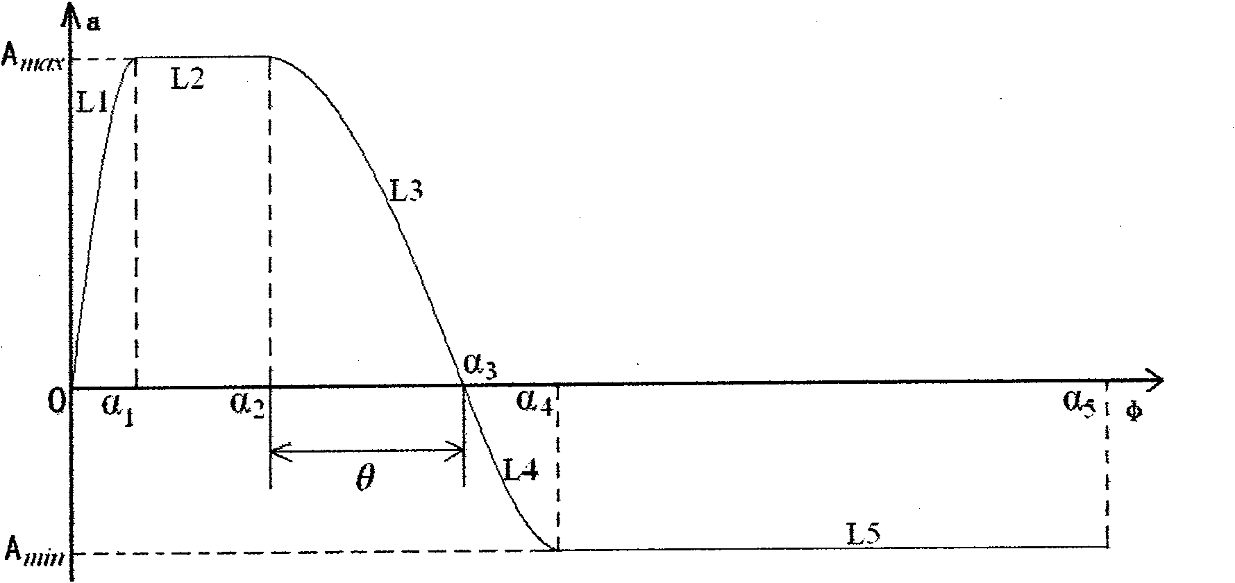
[0016] Here, the 1 / 4 wave sine is taken as an example to illustrate the design method, and the design of ellipse and high-order square line mathematical formulas can be obtained in the same way. figure 2 is the tappet acceleration curve of 1 / 4 wave sine, that is, where L 1 , L 3 , L 4 It is a 1 / 4 wave trigonometric function curve;

[0017] Depend on figure 2 The acceleration curve diagram of can give the acceleration formula, as shown in Mathematical Formula 1:

[0018] [mathematical formula 1]

[0019] a = a 1 = A max sin ( πα 2 α 1 ) ...


PUM


Abstract

The invention discloses an optimal design method for a valve cam profile, which comprises the selection of basic cam design parameters used for optimal design, particularly three parameters, namely the maximum positive acceleration Amax, the maximum negative acceleration Amin and a warp angle theta of a positive acceleration descent stage influencing the flying off of a mechanism. The implementing method comprises the following steps: determining an acceleration curve profile type, selecting a corresponding mathematical curve and calculating a mathematical formula of an acceleration curve; determining a parameter limited range according to the engine design requirement; and finally, according to the mathematical formula of the acceleration curve, performing optimal design in the determined parameter limited range, and determining optimal parameter values and obtained the optimal cam profile. The valve cam profile designed by the design method of the invention has high flying off rotating speed, low maximum contact stress and large time-area value or fullness coefficient.

Description

technical field [0001] The invention belongs to the field of engine design, and relates to a profile design of an air distribution cam, in particular to design a more optimized cam profile according to known cam parameters. Background technique [0002] The gas distribution mechanism is an important part of the internal combustion engine. Its function is to realize the replacement of the cylinder charge between the working cycles, and to open and close the intake and exhaust valves regularly according to the working order of the cylinders, so as to ensure that the cylinders suck in fresh air and discharge combustion. exhaust gas. Common valve trains are all driven by valve cams, and the design of the valve train depends largely on the contour shape of the valve cam. Whether the design of the valve cam is good or not directly affects the performance index of the internal combustion engine. These indicators include not only power and economy, but also operating performance, ...

Claims


Application Information

Patent Timeline
Patent Type & Authority Applications(China)
IPC IPC(8): F01L1/08G06F17/50
Inventor 刘福水杜巍陆滢王长园
Owner BEIJING INSTITUTE OF TECHNOLOGYGY
Why Eureka
Try Eureka