
Automatic card dispenser and automatic card sending method thereof

A technology for automatically issuing cards and cards, which is applied to machines that issue pre-printed tickets, computer parts, instruments, etc., and can solve problems such as inability to access accurate, clear information, damage, size, thickness, and high weight

Active Publication Date: 2010-07-28
IND TECH RES INST
View PDF2 Cites 18 Cited by
  • Summary
  • Abstract
  • Description
  • Claims
  • Application Information

AI Technical Summary

Problems solved by technology

In recent years, radio frequency identification technology (RFID) has risen. In order to pursue safety control and manpower saving, more and more radio frequency identification cards are used to control the entry and exit of people and vehicles. However, most of the methods used are still passive short-range reading. Mainly, the scope of control is mostly limited to access control and fixed-point management. It is still impossible to effectively track anytime and in real time. At the same time, it is impossible to access more accurate and clear information, and it is impossible to dispatch and adjust in response to temporary or emergency situations.
[0003] In order to achieve the above-mentioned correct control, real-time tracking and emergency support dispatch, it is necessary to use active radio frequency cards with more active response and wide-area tracking. However, the size, thickness and weight of such cards may be higher than ordinary cards. High, the general card issuing machine mechanism can't bear it, which leads to failure and damage

Method used


Image

  • Automatic card dispenser and automatic card sending method thereof
  • Automatic card dispenser and automatic card sending method thereof
  • Automatic card dispenser and automatic card sending method thereof

Examples


Embodiment Construction

[0071] The technical solutions of the present invention will be further described in more detail in conjunction with the accompanying drawings and specific embodiments.

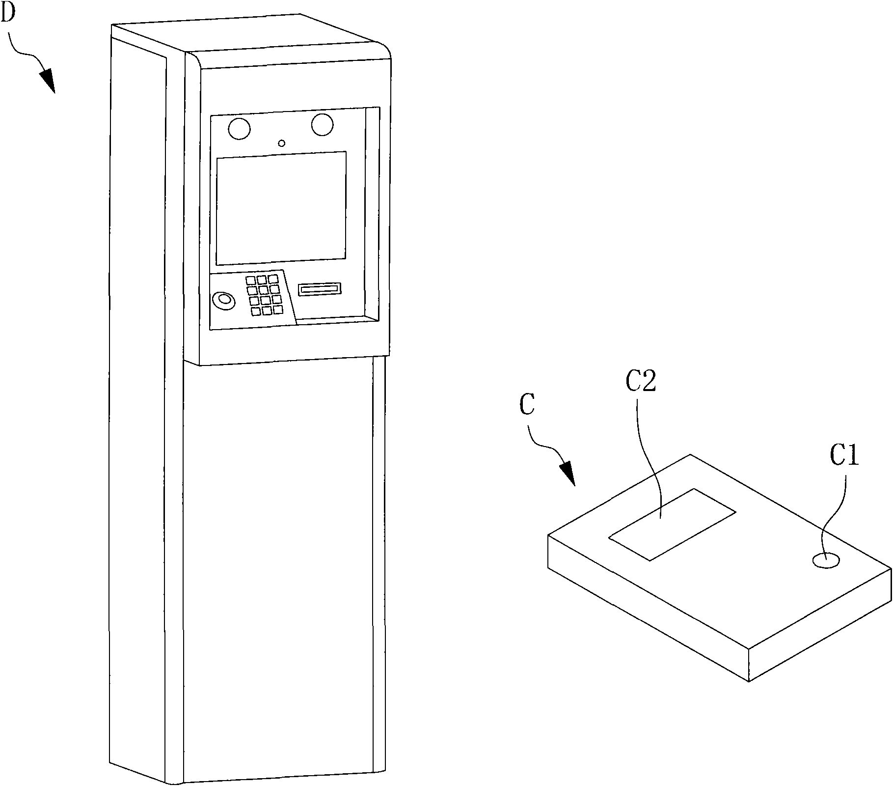
[0072] See figure 1 , which is an appearance diagram of an automatic card issuing machine and the issued cards according to the embodiment of the present invention. The automatic card dispenser D of the present invention is similar to a kiosk. After the user operates, the automatic card dispenser D can send out a card C. The card C is provided with an activation switch C1 and a display screen C2. The automatic card issuing machine according to the technology of the present invention can issue cards whose area is, for example, 8 cm x 6 cm and whose thickness is not less than 0.2 cm.

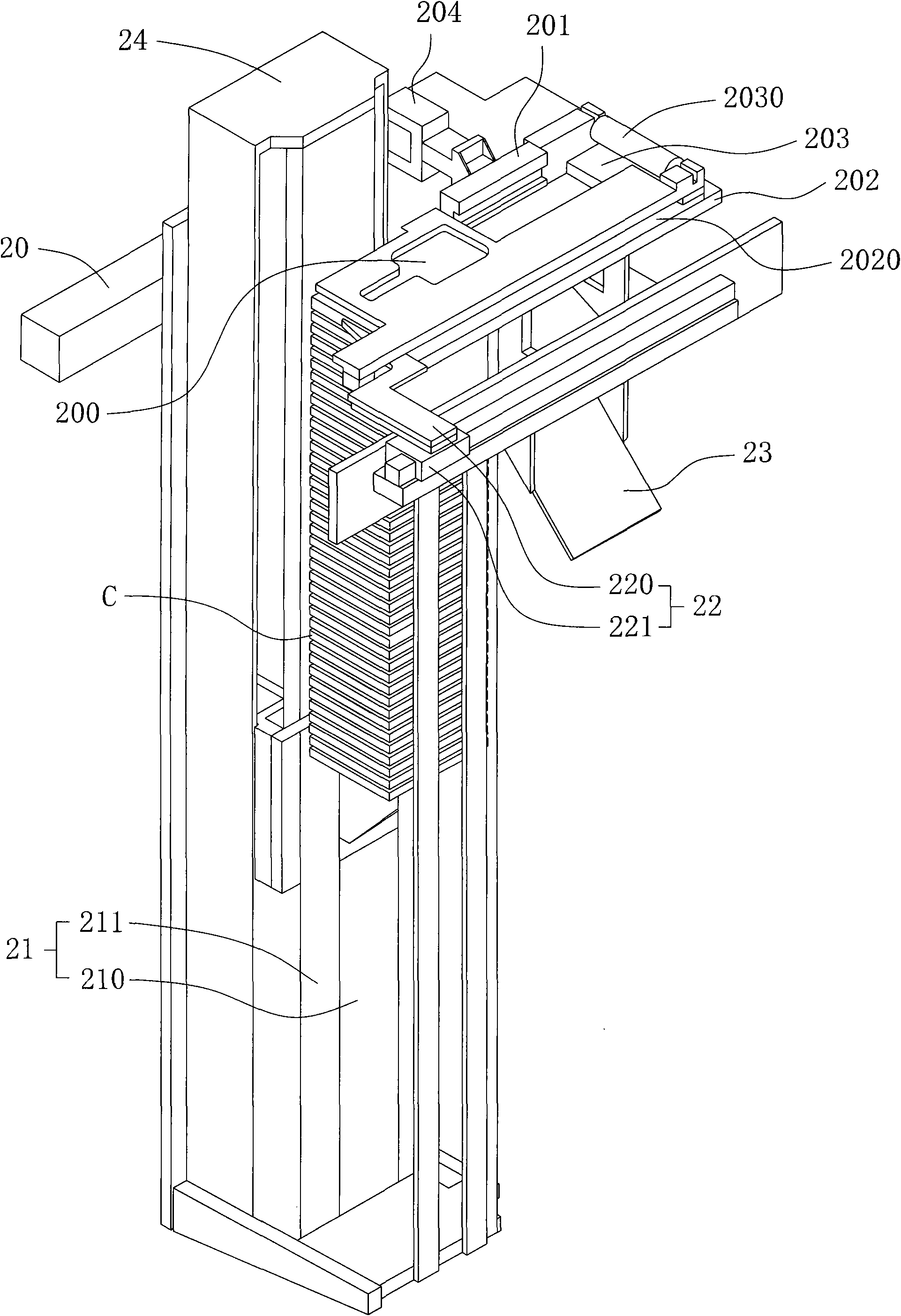
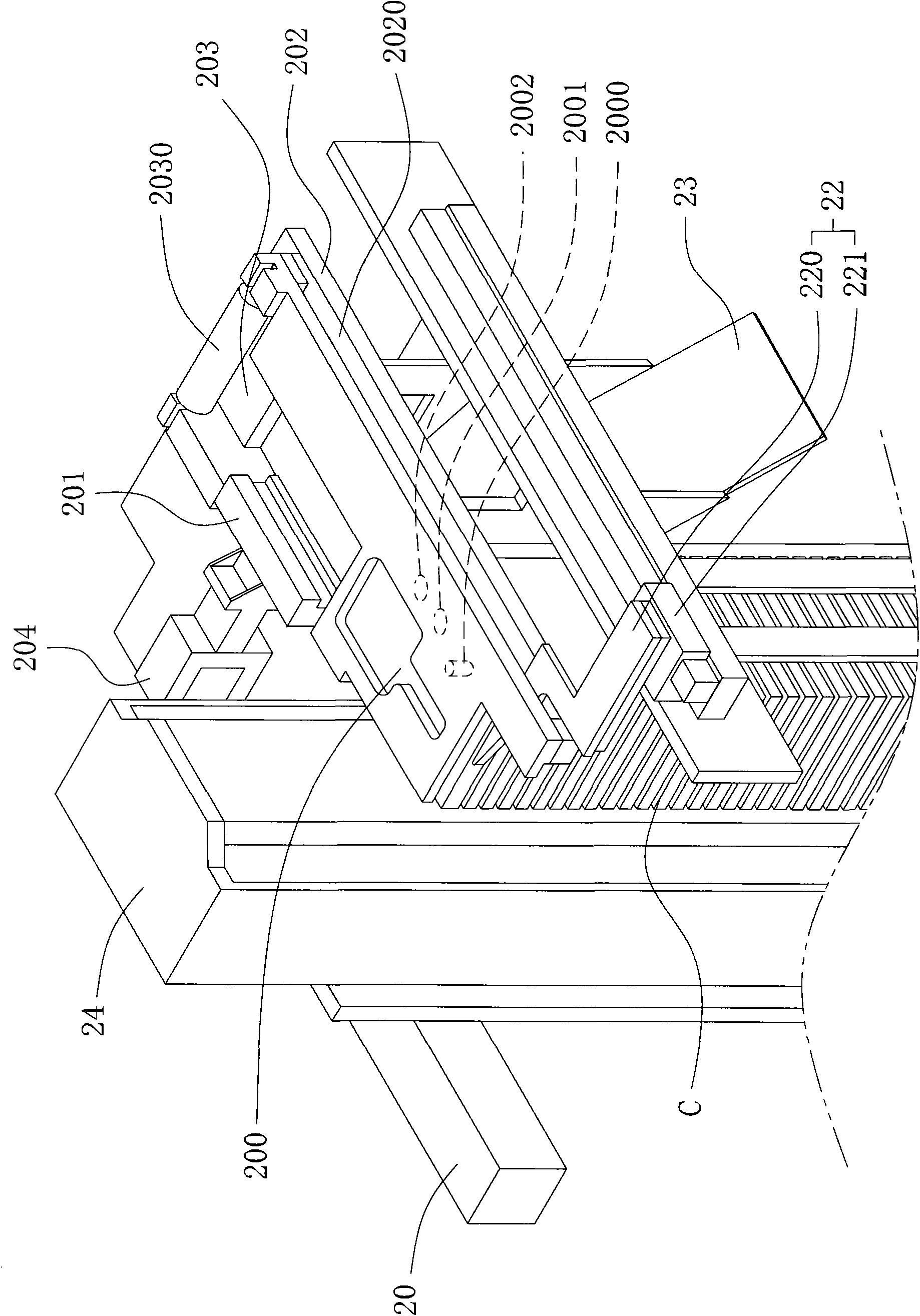
[0073] figure 2 It is a three-dimensional view of the internal structure of the implementation example of the automatic card issuing machine of the present invention, image 3 for figure 2 A partially enlarged perspective v...


PUM


Abstract

The invention discloses an automatic card sender, comprising a base, and a waiting area, an exit area, a first guide rail and a second guide rail which are arranged on the base, wherein the first guide rail and the second guide rail are parallel to each other. The characteristics of the automatic card sender are as follows: the waiting area and the exit area are respectively arranged at two ends of the first guide rail and the second guide rail; two sides of a card to be sent are respectively accommodated in the first guide rail and the second guide rail; the first guide rail can be separatedfrom the waiting area and the exit area; a vertical pushing unit is connected with the base and is provided with a box chamber for containing the card and a vertical driver; a horizontal pushing unit is connected with the base and pushes the card to the exit area along the second guide rail to be contacted with a card press wheel; and a recovery unit is connected with the base and is arranged under the first guide rail.

Description

technical field [0001] The invention relates to an automatic card issuing machine, in particular to an automatic card issuing machine capable of pushing cards in parallel. Background technique [0002] Since the 911 incident in the United States, homeland security has become the primary focus of various countries. Regardless of park security, port security, airport security, etc., they all demand stricter and complete control, especially in the entry and exit and tracking of vehicles and personnel. Up is even more critical. As far as the current operation is concerned, most of the security control is handled manually, including the registration of personnel entering the factory, renewal of certificates, and data verification, etc., are all performed by security personnel or service desk personnel; even with a more automated card issuance control mechanism, Most of them are just simple serial numbers, time data recording and mechanized processing. In recent years, radio fre...

Claims


Application Information

Patent Timeline
IPC IPC(8): G06K13/08G06K13/10G07B3/00
Inventor 范振智陈慧娟郑憬聪谢淑汝余俊德
Owner IND TECH RES INST
Learn More