
Acoustic wave device

一种弹性波装置、弹性波的技术,应用在电气元件、阻抗网络等方向,能够解决高阶模杂散变大、表现高阶模杂散等问题,达到高阶模杂散抑制、频率温度特性改善的效果

Inactive Publication Date: 2010-07-28
MURATA MFG CO LTD
View PDF3 Cites 12 Cited by
  • Summary
  • Abstract
  • Description
  • Claims
  • Application Information

AI Technical Summary

Problems solved by technology

[0014] In addition, as described above in Patent Document 2, SiO 2 When the thickness of the film is increased from 0.24λ to 0.35λ, the spurs caused by higher-order modes will appear more
[0015] Therefore, even in the surface acoustic wave device as described in Patent Document 2, thickening the SiO 2 film, it will also increase the high-order mode spurs, and the improvement of frequency-temperature characteristics and the suppression of high-order mode spurs are in a trade-off relationship

Method used


Image

  • Acoustic wave device
  • Acoustic wave device
  • Acoustic wave device

Examples


Embodiment Construction

[0070] Hereinafter, the present invention will be clarified by describing specific embodiments of the present invention with reference to the drawings.

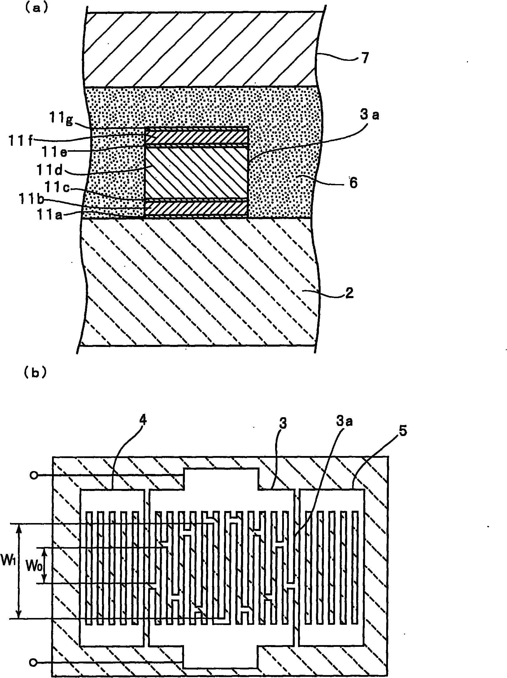
[0071] figure 1 (a) is a partial cutaway enlarged front sectional view of a boundary acoustic wave device according to an embodiment of the present invention, figure 1 (b) is a schematic plan view showing the electrode structure of the boundary acoustic wave device.

[0072] Such as figure 1 As shown in (a), the boundary acoustic wave device 1 has LiNbO 3 Composed of piezoelectric body 2. SiO is laminated on the piezoelectric body 2 2 Layer 6.

[0073] In Piezoelectric 2 and SiO 2 The IDT electrode 3 is formed on the interface of the layer 6 . exist figure 1 In (a), one electrode finger portion of the IDT electrode 3 is shown in an enlarged cross-sectional view. In fact, if figure 1 As shown in (b), the IDT electrode 3 and the reflectors 4 and 5 arranged on both sides of the IDT electrode 3 in the propagation d...


PUM


Abstract

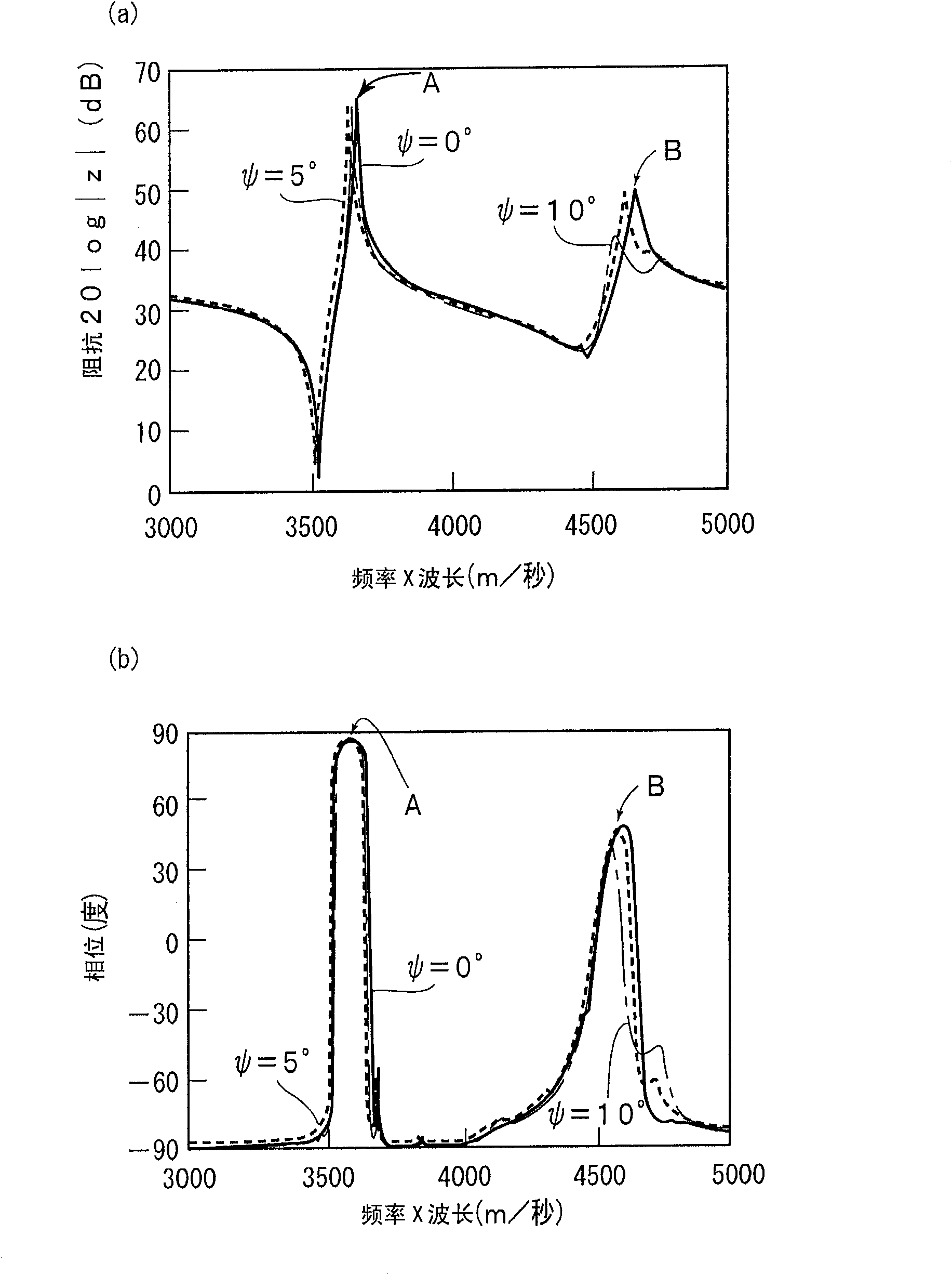
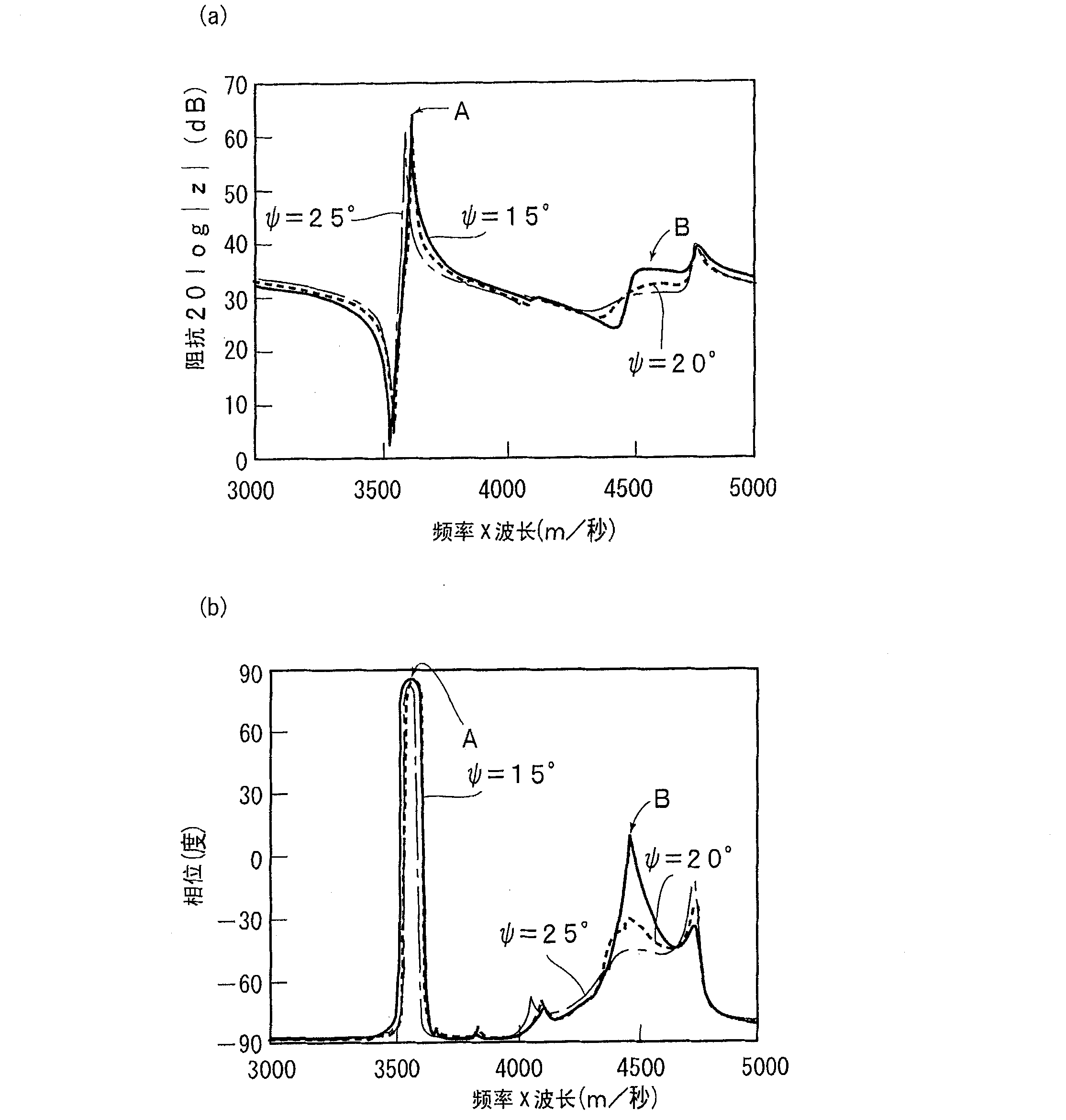
An acoustic wave device having an improved frequency-temperature characteristic and in which a spurious response of the higher order mode is suppressed includes a piezoelectric substrate (2) made of LiNbO3, a SiO2 layer (6) laminated on the piezoelectric substrate (2), and an IDT electrode (3) disposed in an interface of the piezoelectric substrate (2) and the SiO2 layer (6), wherein [phi] and [theta] of Euler angles expressed by ([phi], [theta], [psi]) of LiNbO3 substrate satisfy [phi]=0 DEG and 80 DEG <=[theta]<=130 DEG , respectively. The acoustic wave device using an acoustic wave primarily having an SH wave, wherein [psi] is set to satisfy 5 DEG <=[psi]<=30 DEG .

Description

technical field [0001] The present invention relates to an elastic wave device used for a resonator or a bandpass filter, etc., and more specifically relates to a device having a piezoelectric body using LiNbO 3 , layered SiO on the piezoelectric body 2 An elastic wave device with a structure such as a dielectric body. Background technique [0002] Conventionally, elastic wave devices such as boundary acoustic wave devices and surface acoustic wave devices have been used as bandpass filters and the like in communication equipment. [0003] An example of such a boundary acoustic wave device is disclosed in Patent Document 1 below. Figure 24 as well as Figure 25 It is a plan view for explaining the boundary acoustic wave device described in Patent Document 1, and a schematic partially cutout enlarged cross-sectional view showing its essential parts. [0004] The boundary acoustic wave device 1001 has LiNbO 3 Substrate 1002. In LiNbO 3 IDT electrodes 1003 are formed on ...

Claims


Application Information

Patent Timeline
Patent Type & Authority Applications(China)
IPC IPC(8): H03H9/64H03H9/145
CPCH03H9/02669H03H9/02834H03H9/02559H03H9/0222H03H9/131H03H9/14541
Inventor 三村昌和
Owner MURATA MFG CO LTD
Learn More