Determinant linear array coordinate scanning circuit
A scanning circuit and determinant technology, which is applied in the field of determinant linear array coordinate scanning circuit, can solve the problems of difficult implementation, limited scanning lines, occupying MPU processing time, etc., and achieve the effects of good versatility, simple design and convenient implementation
- Summary
- Abstract
- Description
- Claims
- Application Information
AI Technical Summary
Problems solved by technology
Method used
Image
Examples
Embodiment Construction
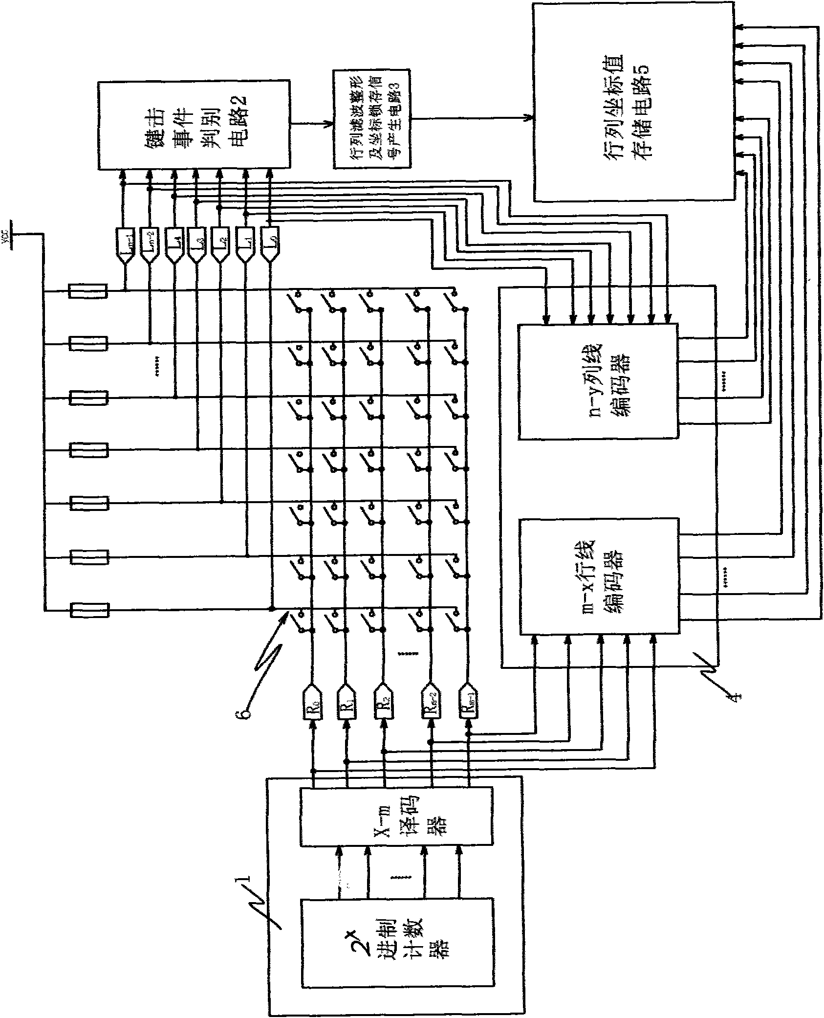
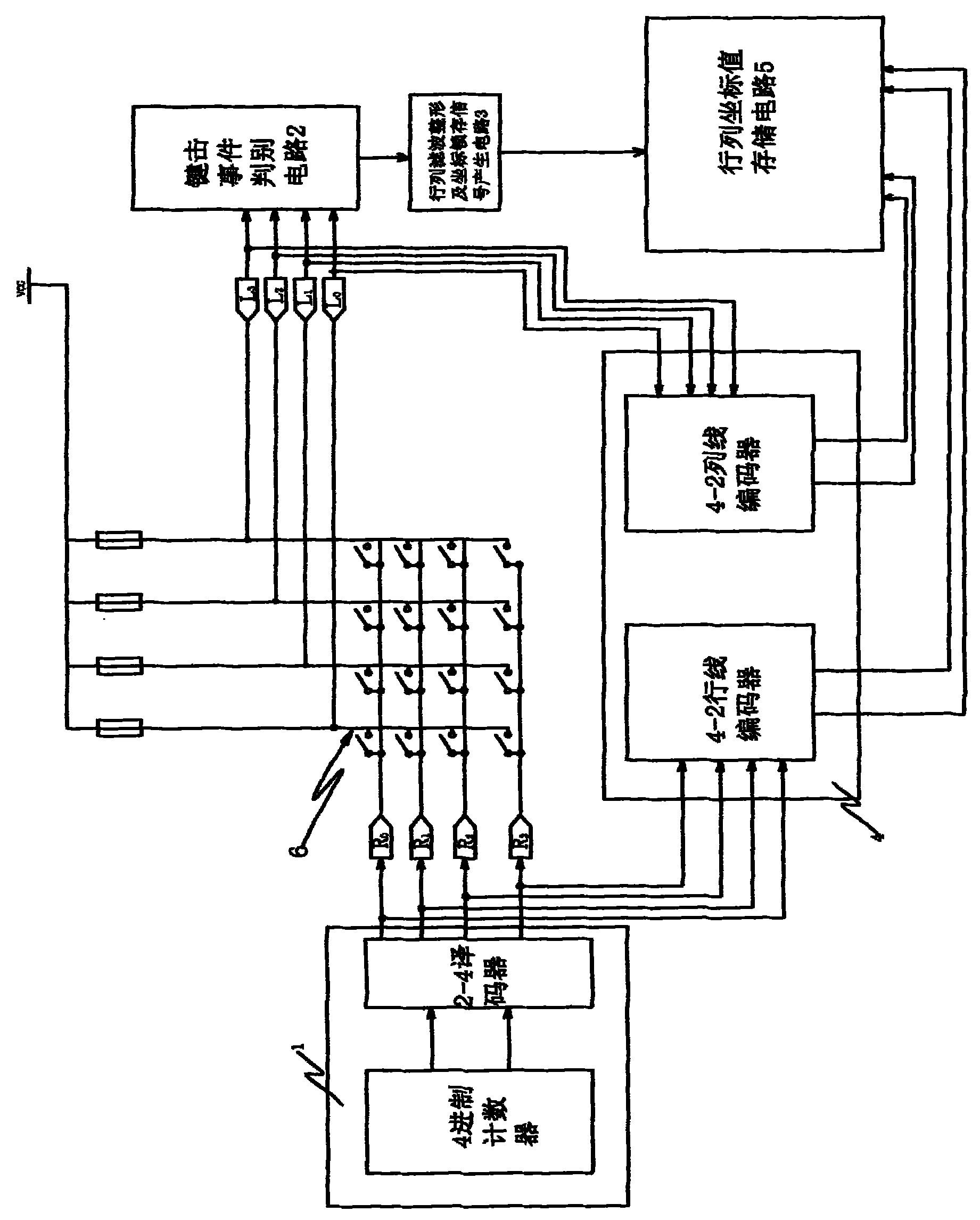
[0034] see figure 1 , the present invention is a determinant linear array coordinate scanning circuit, which includes: an m-channel pulse distribution circuit 1, a keystroke event discrimination circuit 2, a row and column signal filter shaping and coordinate latch signal generation circuit 3, and a row and column coordinate encoding circuit 4 and a row and column coordinate value storage circuit.
[0035] figure 1 The shown m×n matrix button circuit 6 is a line array structure in which m row lines and n column lines are arranged horizontally and vertically, wherein m and n are natural numbers. The connected buttons, so there are m×n buttons in total, and the line port R 0 ~R m-1 It is the input terminal of the row line, which is also the input terminal of the scanning signal; the column line port L 0 ~ L n-1 It is the output terminal of the column line, that is, the output terminal of the scanning signal; the n column lines are respectively connected to the power supply ...
PUM
 Abstract
Description
Claims
Application Information
 - R&D
- Intellectual Property
- Life Sciences
- Materials
- Tech Scout
- Unparalleled Data Quality
- Higher Quality Content
- 60% Fewer Hallucinations
Browse by: Latest US Patents, China's latest patents, Technical Efficacy Thesaurus, Application Domain, Technology Topic, Popular Technical Reports.
© 2025 PatSnap. All rights reserved.Legal|Privacy policy|Modern Slavery Act Transparency Statement|Sitemap|About US| Contact US: help@patsnap.com


