Electrical contact

A technology of electrical contacts and contacts, applied in the direction of circuits, electrical components, coupling devices, etc., can solve problems such as damage, damage to plug contacts, and hinder the manufacture of cables, so as to prevent winding and simplify production

Active Publication Date: 2010-07-28
TE CONNECTIVITY GERMANY GMBH
View PDF2 Cites 9 Cited by
  • Summary
  • Abstract
  • Description
  • Claims
  • Application Information

AI Technical Summary

Problems solved by technology

This hampers the manufacture of cables and in some cases can lead to damage to the plug contacts, which are constantly getting smaller due to the desire to miniaturize and therefore the thickness of the stamped steel sheets is getting thinner and thus more susceptible to damage

Method used


Image

  • Electrical contact
  • Electrical contact
  • Electrical contact

Examples


Embodiment Construction

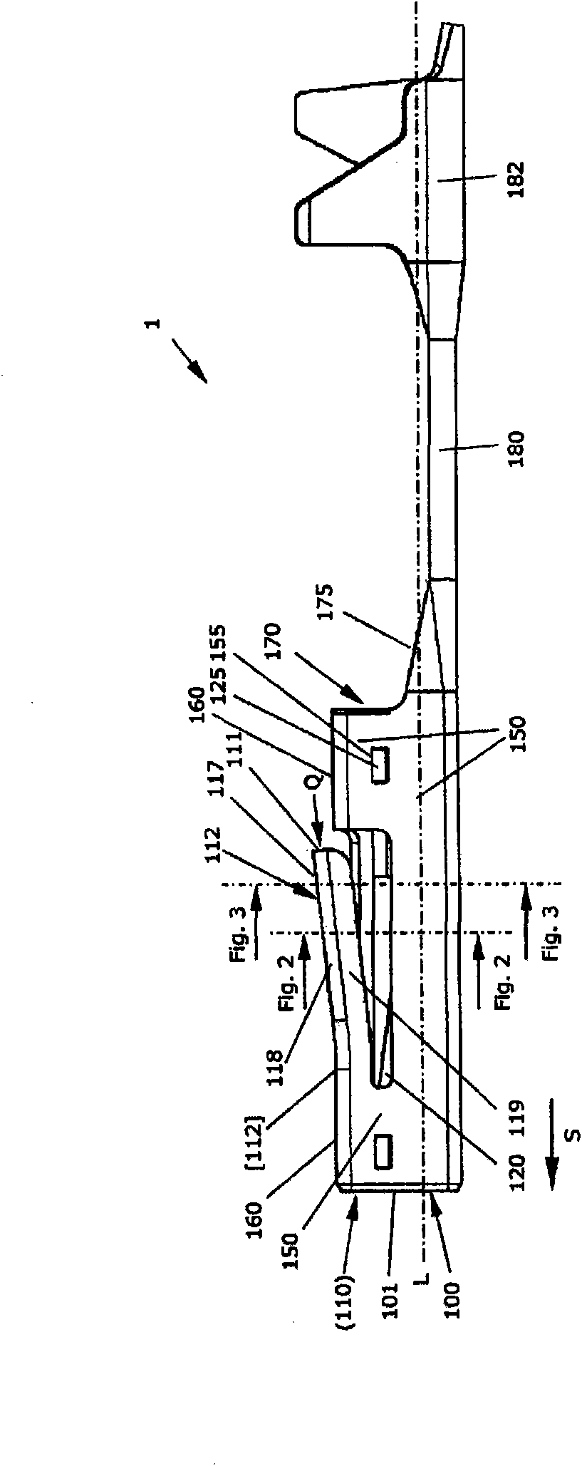
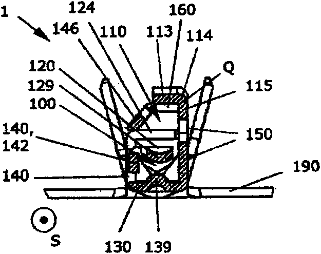
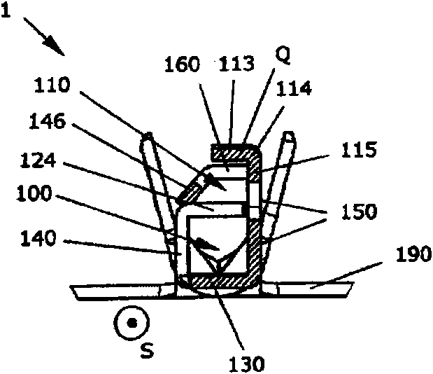
[0033] The invention is described in more detail below with reference to an electrical plug contact for an electrical plug-in connector system in the automotive sector. However, the invention is not intended to be limited to this electrical socket contact, but relates to other electrical contacts such as tab receptacle or pin electrical contacts. In principle, the invention can be used as long as the electrical contacts are locked, for example in a housing, by means of retaining springs.

[0034] The following discussion refers to the front or rear of the electrical contacts. In this case, front is intended to mean a position on the electrical contact near the free end of the contact box or near the free end of the interlock box of the electrical contact. Correspondingly, the rear part denotes a position on the plug contact arranged at a distance from the free end of the contact box or interlock box.

[0035] shown in figure 1 The electrical contact 1 according to the inven...


PUM


Abstract

The invention relates to an electrical contact, in particular an electrical socket contact (1), having a catch spring (112) projecting therefrom for latching the electrical contact (1) in a housing, wherein over substantially its entire extent in the direction of a longitudinal axis (L) of the electrical contact (1), the catch spring (112) is assembled with regard to its cross-section (Q) from at least two areas (113, 115), which are arranged bent relative to one another by means of a transitional area (114) or are connected together in such a manner that they merge continuously.

Description

technical field [0001] The present invention relates to an electrical contact, preferably, to a miniaturized electrical contact, in particular to an electrical plug contact, which has a protrusion protruding from the contact for locking the electrical contact in a housing The catch spring in the body. The invention also relates to a manufactured cable having an electrical contact according to the invention. Background technique [0002] Such an electrical plug contact comprises a connection area for the electrical leads and an insertion area with a contact box, wherein the contact box forms a receiving space for a pin electrical contact. The contact box generally comprises a base plate with two side walls, the upper free edge of one side wall being bent over the base plate. When a pin contact is inserted into said socket contact, the base plate and side walls of the contact box mechanically fix the pin contact into the socket contact, preferably via contact springs located...

Claims


Application Information

Patent Timeline
Patent Type & Authority Applications(China)
IPC IPC(8): H01R13/432
CPCH01R13/432H01R13/113
Inventor 克里斯琴·伯梅尔罗尔夫·杰特
Owner TE CONNECTIVITY GERMANY GMBH
Why Eureka
Try Eureka