Minitype drill bit and processing method thereof

A micro-drill and micro-drill technology, which is applied in metal processing equipment, drilling/drilling equipment, boring machine/drilling machine parts, etc., can solve the problem of unbalanced drilling force, unfavorable hole position accuracy, and affecting hole position Performance and other issues, to achieve the effect of good balance, improved wear resistance, and long processing life

Active Publication Date: 2010-08-04
SHENZHEN JINZHOU PRECISION TECH
View PDF5 Cites 38 Cited by
  • Summary
  • Abstract
  • Description
  • Claims
  • Application Information

AI Technical Summary

Problems solved by technology

Since the cutting edge of the single-edge single-groove micro-drill is a single one, the force on the drill point is unbalanced, which will generate radial force and

Method used


Image

  • Minitype drill bit and processing method thereof
  • Minitype drill bit and processing method thereof
  • Minitype drill bit and processing method thereof

Examples


Embodiment Construction

[0038] The present invention will be further described below in conjunction with the accompanying drawings and preferred embodiments.

[0039] The technical solution of the present invention can be applied to micro-drills with more than double blades. Below, the micro-drills with double-blades and double grooves with a diameter of less than 6.5mm are used as an example to illustrate.

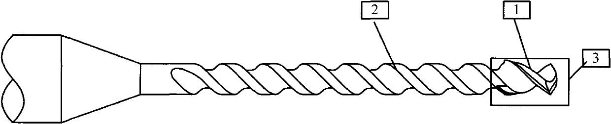
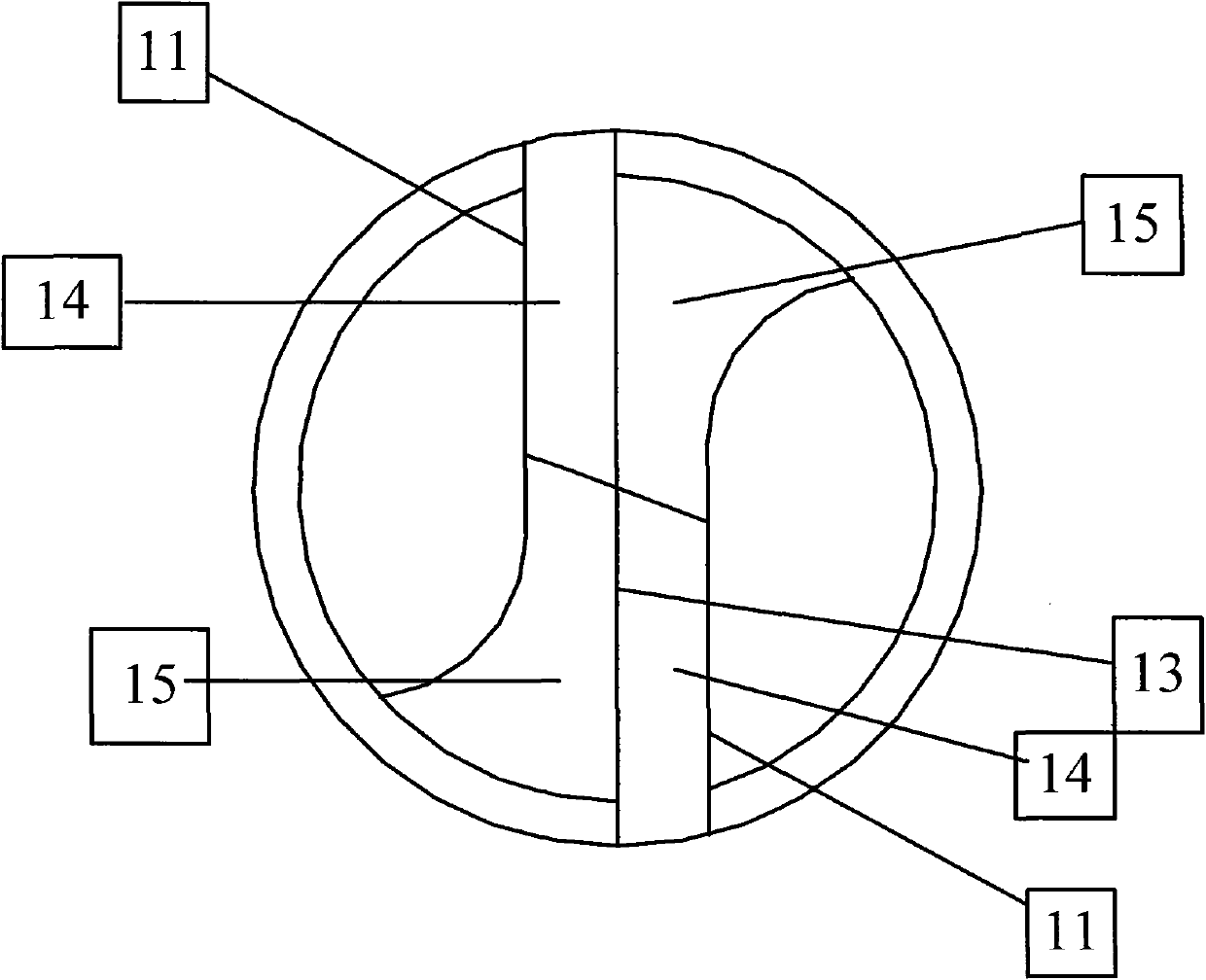
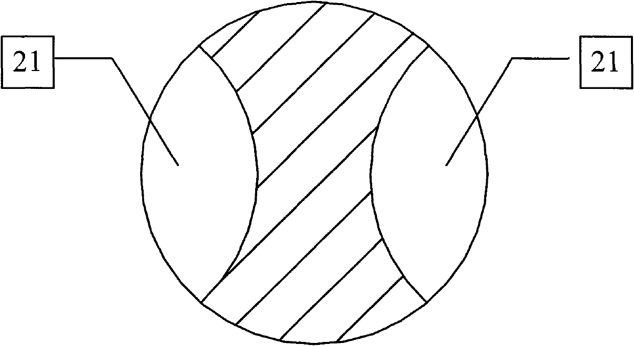
[0040] The structure of the micro-drill of described double-edged double groove is as Figure 5-11 As shown, it includes a drill tip 41 and a drill body 42, and the drill tip 41 includes two main cutting edges, two main cutter faces, and two auxiliary cutter faces (not shown in the figure) symmetrical along the axis of the micro-drill. The structure is the same as that of conventional micro drills; the drill body 42 is provided with two spirally rising chip flutes (44, 45). There are two helically rising chip flutes of the drill body, including a long chip flute 44 and a short chip flute 45, an...


PUM


Abstract

The invention discloses a minitype drill bit and a processing method thereof. The minitype drill bit comprises a drill point and a drill body, wherein the drill point comprises two main cutting edges which are symmetrical by the axle center of a minitype drill, two main cutter surfaces and two auxiliary cutter surfaces; and the drill body is provided with two spiral rising chip flutes, wherein the chip flutes are respectively a long chip flute and a short chip flute which have different helical angles so as to change the two chip flutes into a converging state from a separated state; and the short chip flute is finished at the joint part with the long chip flute. As the two chip flutes on the drill body of the minitype drill bit are set to be the long chip flute and the short chip flute which have the different helical angles, and the short chip flute is finished at the joint part with the long chip flute, most part of the drill body is the single long chip flute. Therefore, the rigid part of a flute body is increased, the core thickness thereof is thickened, and the rigidity of the drill body part of the minitype drill is better.

Description

technical field [0001] The invention relates to the field of manufacturing micro-drills, more specifically, to a micro-drill and a method for processing the micro-drill. Background technique [0002] The structure of the commonly used micro drill bit is as follows: Figure 1-Figure 3 As shown, the micro drill includes a drill point 1 and a drill body 2, and the shape of the drill point is as follows figure 2 As shown, there are two symmetrical main cutting edges 11, a chisel edge between the two main cutting edges, and two helical secondary cutting edges positioned at the rear side of the main cutting edge; the main cutting edge The first relief surface 14 and the second relief surface 15 as shown in the figure are respectively formed between the minor cutting edge and the chisel edge; between the first relief surface 14 and the second relief surface 15 A line of intersection 13 is formed, the length of which is approximately the same as the diameter of the drill body. Th...

Claims


Application Information

Patent Timeline
IPC IPC(8): B23B51/02B23P15/32
CPCB23B2251/046B23B51/02B23B2251/426B23B51/011B23B51/00B23B47/34B23P15/32
Inventor 厉学广屈建国邹卫贤
Owner SHENZHEN JINZHOU PRECISION TECH
Why Eureka
Try Eureka