
Manufacturing method and manufacturing apparatus for twisted flat bar

一种螺旋扁钢、制造装置的技术,应用在螺旋扁钢的制造及制造装置领域,能够解决损害美感、难制造螺旋扁钢、难变钢施加均匀的扭转力等问题

Inactive Publication Date: 2010-08-04
后藤常郎
View PDF3 Cites 7 Cited by
  • Summary
  • Abstract
  • Description
  • Claims
  • Application Information

AI Technical Summary

Problems solved by technology

[0008] However, although the pitches of the conventional flat steel helicals are consistent visually, the dimensions of each pitch are different when measured accurately. , the nut is stuck due to the deviation of the pitch of the spiral flat steel, and it is difficult to make the relative movement of the nut relative to the spiral flat steel.
[0009] In addition, in the case of arranging a plurality of spiral flat steels in parallel and using them for wall surface decoration, etc., slight deviations in the pitch can be clearly judged, resulting in greatly degrading the aesthetics.
[0010] There are two reasons for this pitch inconsistency: (1) it is caused by the unevenness of the material of the flat steel; (2) in the method of twisting the two ends of the flat steel as in Patent Document 3, the spiral flat steel When the length becomes longer, it is difficult to apply uniform torsional force to the entire variable steel
In particular, when the length of the spiral flat steel becomes longer, both of the above two factors may work, and it is extremely difficult to manufacture a long spiral flat steel with a uniform pitch.

Method used


Image

  • Manufacturing method and manufacturing apparatus for twisted flat bar
  • Manufacturing method and manufacturing apparatus for twisted flat bar
  • Manufacturing method and manufacturing apparatus for twisted flat bar

Examples


Embodiment Construction

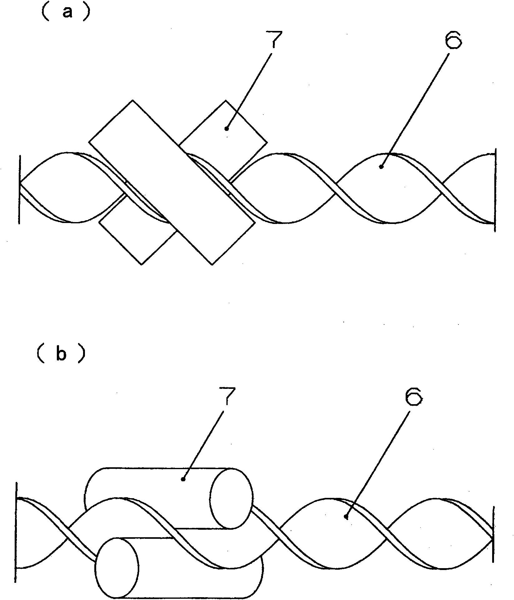
[0060] The manufacturing method of the spiral flat steel of the present invention is characterized in that two round steels arranged obliquely at the same angle to different directions with respect to the longitudinal direction of the flat steel sandwich the two faces of the flat steel, and the above two The round bar is relatively rotated with respect to the flat bar with the longitudinal direction as the rotation axis, and the flat bar is relatively moved in the longitudinal direction with respect to the round bar.

[0061] Next, the manufacturing method and manufacturing apparatus of the spiral flat steel of this invention are demonstrated in detail.

[0062] figure 1 It is a diagram showing the arrangement relationship of spiral flat steel and round steel, figure 1 (a) represents a top view, figure 1 (b) shows a front view.

[0063] The present invention is characterized in that the flat bar is twisted using two round bars arranged obliquely in different directions a...


PUM


Abstract

Intended is to provide twisted flat bar manufacturing method and apparatus, which can suppress the dispersion of pitches and which can work even a long flat bar into a twisted flat bar. The twisted flat bar manufacturing method is characterized in that a flat bar (5) is clamped on its two faces by two round bars (7) which are arranged at an equal direction but in different direction with respect the longitudinal direction of the flat bar, in that the two round bars are rotated on that longitudinal direction relative to the flat bar, and in that the flat bar is moved in that longitudinal direction relative to the round bars.

Description

technical field [0001] The invention relates to a method and a device for twisting a flat bar to produce a helical flat bar. Background technique [0002] Spiral flat bars made from twisted flat bars are made e.g. Figure 17 The shape shown by reference numeral 6 can be made of iron, aluminum, stainless steel or the like. [0003] This spiral flat steel can be used as anchors buried in the ground for fixing structures such as seats and signs on the ground. In recent years, it can be used as foundation piles for pillars constituting large buildings. As shown in 1 or 2, it can be used as a part of the conveying mechanism constituting the conveying device, and as an decoration inside and outside the building. [0004] Patent Document 1: Japanese Patent Application Laid-Open No. 10-61742 [0005] Patent Document 2: Japanese Patent Laid-Open No. 2001-136844 [0006] As the manufacturing method of this spiral flat steel, as also disclosed in Patent Document 3, first, as Figure...

Claims


Application Information

Patent Timeline
Patent Type & Authority Applications(China)
IPC IPC(8): B21D11/14
CPCB21D11/14
Inventor 后藤常郎
Owner 后藤常郎
Learn More