Catalytic heater

A catalytic converter and heating system technology, applied in the field of catalytic heating systems, can solve the problems of limited practicality of batteries, and achieve the effect of catalytic ignition and high-efficiency catalytic ignition

Inactive Publication Date: 2010-08-04
HEATGEAR PROFESSIONAL
View PDF3 Cites 14 Cited by
  • Summary
  • Abstract
  • Description
  • Claims
  • Application Information

AI Technical Summary

Problems solved by technology

But the need to heat the ceramic-based catalyst means a fairly strong power source
Heavy battery limits utility if used in portable systems that are good for hikers and military purposes

Method used


Image

  • Catalytic heater
  • Catalytic heater
  • Catalytic heater

Examples


Embodiment Construction

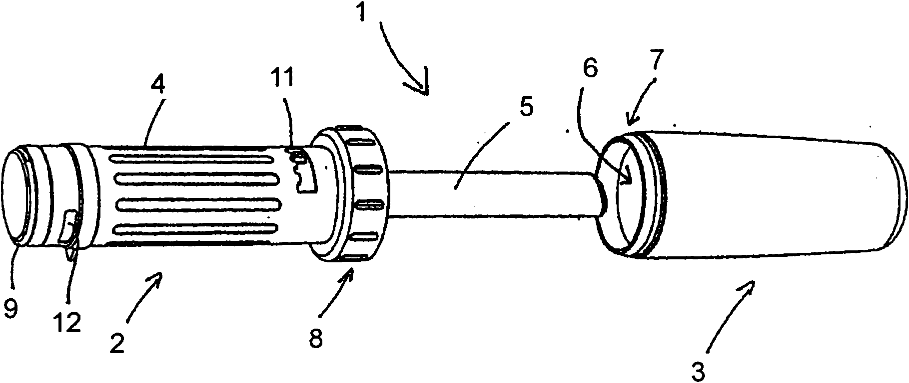
[0101] Figure 1 shows a heating system 1 according to the invention. The heating system 1 includes a heating unit 2 and a protective container 163 . The heating unit 2 has a handle 4 for connecting the heating unit 2 and a heating tube 5 which can emit heat radiation from a catalytic element housed in the heating tube 5 . When the heating system is not in use, the heating tube 5 may be fitted in the protective container 163 . The container 163 can also be used to store fluid or other materials related to heating with the heating tube 5 such as powder, or to form a storage container for fluid or other materials during transportation and use. The container 163 can be used for hot fluid and function as an insulated bottle, or to warm hands by holding the container 163 . To reduce the energy output to the environment, the container 163 may be insulated.

[0102] The container 163 has an upper opening 6 and a thread 7 corresponding to an internal thread (not shown) of the adapter ...


PUM


Abstract

A catalytic heating system comprising a main catalyst (20, 50) for flameless catalytic burning of fuel gas and a triggering system for initiating the catalytic burning, the triggering system comprising an electrical power source electrically connected to a metallic catalyst portion (104). As electric current flows through the metallic catalyst portion, it is in itself heated as an electric resistance heater to a temperature necessary for triggering the catalytic burning. By using electrical current for direct heating of a catalyst portion, reaction starts as soon as the resistance heating achieves the temperature for initiating the catalytic reaction. As soon as the reaction starts, it is transferred to the main catalyst.

Description

technical field [0001] The present invention relates to a catalytic heating system comprising a primary catalyst for flameless catalytic ignition of a combustible gas and a trigger system for initiating catalytic ignition, said triggering system comprising electrical connection to a resistive heater to partially heat the catalyst to the power supply at the temperature required to trigger the catalytic ignition. Background technique [0002] Catalytic heating for hot water supply is well known in the art and is described in US patents such as 4,510,890 to Cowan, 4,886,017 to Viani and 5,709,174 to Ledjeff, among others. Ignition of the fuel by combustion can be easily initiated by a piezoelectric spark, but it is very difficult to initiate ignition of the fuel by such simple means, especially when the size of the system is small. In order to start the flameless catalytic oxidation of fuel, a temperature of typically 150° C. for said catalytic ignition must first be achieved....

Claims


Application Information

Patent Timeline
Patent Type & Authority Applications(China)
IPC IPC(8): F23C3/00F23C13/02F23D14/10F23D14/18
CPCF23D2203/101F23D14/105F23C13/02F23D14/18F23D2203/1012F23D2213/00F23C3/002F23C3/004Y02E20/34
Inventor H·J·默勒F·G·默勒
Owner HEATGEAR PROFESSIONAL
Why Eureka
Try Eureka