Drawer sliding track

A sliding rail and drawer technology, which is applied to drawers, furniture parts, household appliances, etc., can solve problems such as the loss of self-opening function of the drawer sliding rail, the deformation of the contact head of the pendulum block, and the unsatisfactory user, and achieves a simple and reasonable structure. The effect of eliminating sound, avoiding deformation or breaking

Active Publication Date: 2010-08-11
伍志勇
View PDF5 Cites 59 Cited by
  • Summary
  • Abstract
  • Description
  • Claims
  • Application Information

AI Technical Summary

Problems solved by technology

This drawer slide can be opened automatically, but if the drawer is forcibly pulled out due to user misoperation, the contact head on the swing block will be deformed or broken, a

Method used


Image

  • Drawer sliding track
  • Drawer sliding track
  • Drawer sliding track

Examples


no. 1 example

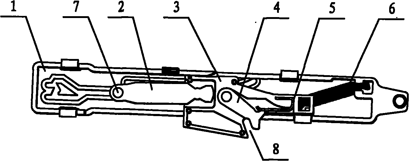
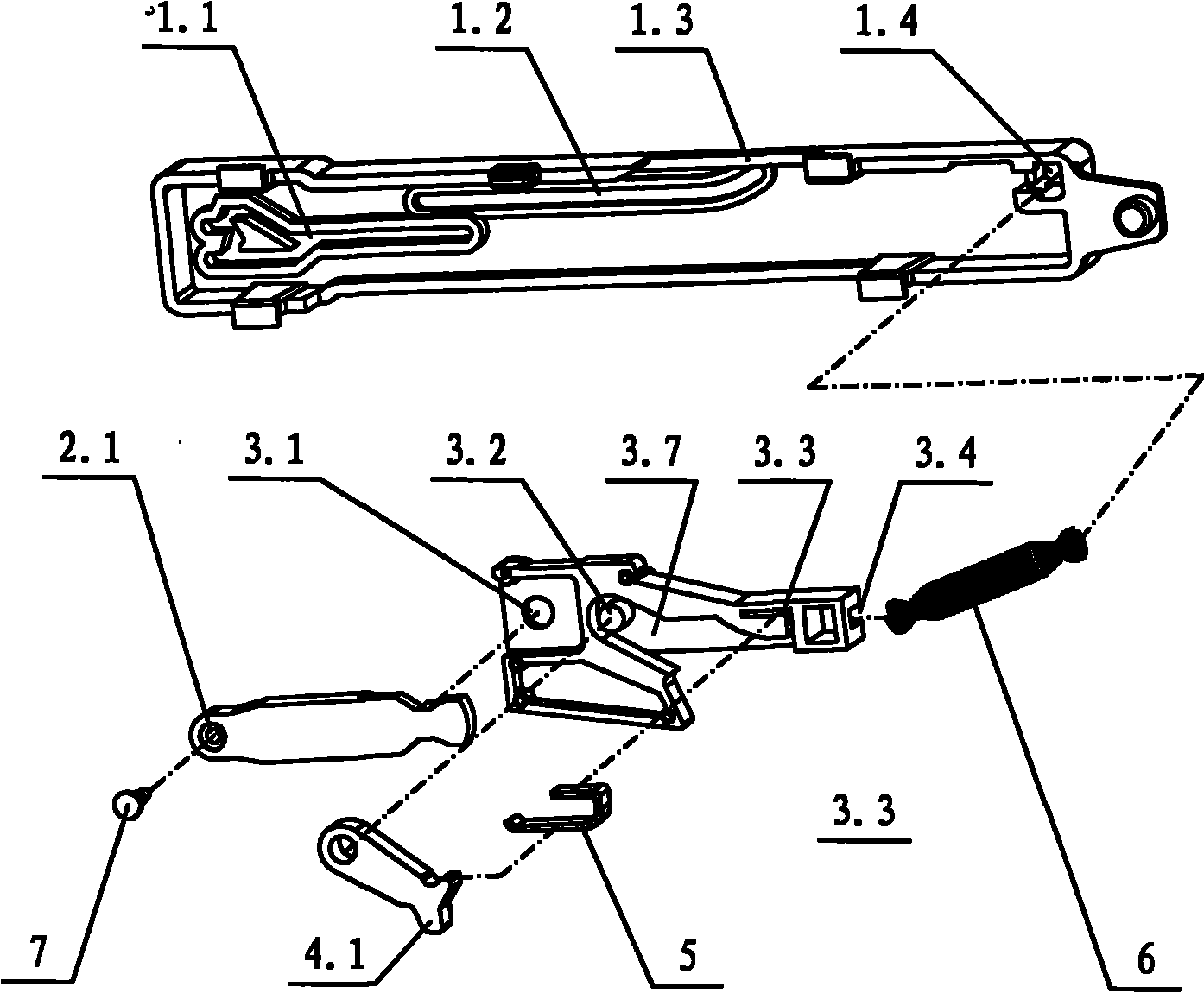
[0043] see Figure 1-Figure 5 and Figure 22 , the drawer slide rail includes a fixed slide rail 10 and a moving slide rail 11, the slide seat 1 is arranged on the fixed slide rail 10, the slide seat 1 is provided with an inner slide groove 1.1, a slide arm 2 and a pendulum block 3, the slide arm One end is connected with the pendulum block, and the other end of the sliding arm is inserted into the inner chute to slide. The pendulum block is provided with an open slot 8, which corresponds to the touch bar 11.1 arranged on the moving slide rail 11. The pendulum block and the pull One end of the spring 6 is connected, and the other end of the tension spring is connected with the sliding seat. The swing block is provided with a cavity 3.7 for the swing arm. One end is provided with a touch head, an open slot is formed between one side of one end of the swing arm and the swing block, the other side of one end of the swing arm is elastically connected with the inner wall of the ca...

no. 2 example

[0050] see Figure 6-Figure 7 and Figure 22 , The cavity 3.7 is provided with a compression spring 9, the other side of one end of the first swing arm is pressed against one end of the compression spring, and the other end of the compression spring is in contact with the inner wall of the cavity. The compression spring in this embodiment can be a post spring, a tower spring, etc. Of course, the compression spring in this embodiment can also be replaced by a tension spring, and the same technical effect as that in this embodiment can be obtained only after the installation position of the tension spring is limited.

[0051] See the first embodiment for the rest of the undescribed parts, and will not repeat them here.

no. 3 example

[0053] see Figure 8-Figure 9 and Figure 22 , the swing arm in this embodiment is the second swing arm 14, the swing block 3 is provided with a pin shaft 3.2, the other end of the second swing arm is pivoted on the swing block through the pin shaft, one end of the second swing arm The other side is in contact with the inner wall of the cavity through the second elastic head 14.2 integral with it. In this embodiment, the second swing arm is integrally formed with the second elastic head 14.2.

[0054] See the first embodiment for the rest of the undescribed parts, and will not repeat them here.


PUM


Abstract

The invention relates to a drawer sliding track which comprises a fixing sliding track and a movable sliding track. A sliding seat is arranged on the fixing sliding track and is internally provided with an inner chute, a sliding arm and a swinging block; one end of the sliding arm is connected with the swinging block, and the other end of the sliding arm is inserted into the inner chute to slide; the swinging block is provided with an open groove which corresponds to a touch bar arranged on the movable sliding track; the swinging block is connected with one end of an extension spring, and the other end of the extension spring is connected with the sliding seat; the swinging block is provided with a cavity for accommodating a swinging arm; the open groove is formed between one side at one end of the swinging arm and the swinging block; the other side at one end of the swinging arm is elastically connected with the inner wall of the cavity; the other end of the swinging arm is pivoted on the swinging block; the swinging arm is a first swinging arm; the swinging block is provided with a pin shaft; the other end of the first swinging arm is pivoted on the swinging block by the pin shaft; and the cavity is internally provided with an elastic piece, a pressure spring or a torsion spring. The drawer sliding track has the characteristics of simple and reasonable structure, flexible operation, high safety, small sound during opening and closure, long service life and wide application range.

Description

technical field [0001] The invention relates to a drawer slide rail. Background technique [0002] Chinese Patent Document No. CN 200956911 Y disclosed a self-opening device for a drawer slide rail on October 10, 2007. The drawer slide rail includes a fixed slide rail and a moving slide rail. It is equipped with a chute, a sliding arm and a pendulum block. One end of the sliding arm is connected to the pendulum block, and the other end is driven into the chute to slide. The chute includes an inner chute for the sliding arm to slide and an outer slide for the pendulum block to slide. The pendulum block is connected to one end of the spring, the other end of the spring is clamped on the slide seat, and the spring is arranged obliquely in the slide seat; the inner chute is a ring-shaped closed structure, and a positioning block is arranged inside, and one end of the positioning block is provided with a The wavy convex, concave and convex joint surface, the inner chute is set a...

Claims


Application Information

Patent Timeline
IPC IPC(8): A47B88/04A47B88/12
Inventor 伍志勇
Owner 伍志勇
Why Eureka
Try Eureka