
Pneumatic holding device of lighter

A technology for lighters and pneumatic clamps, which is applied in the direction of combustion ignition, lighting and heating equipment, and combustion methods, which can solve problems such as high labor intensity, and achieve the effects of simple exhaust gas treatment, low pollution cost, and simple structure

Active Publication Date: 2011-09-07
HANGZHOU YOUNG INSTR SCI & TECH
View PDF0 Cites 0 Cited by
  • Summary
  • Abstract
  • Description
  • Claims
  • Application Information

AI Technical Summary

Problems solved by technology

Most of the existing quality inspection methods for lighters are manual inspection methods. The staff hold the lighter, observe the height of the flame, feel the pressing force, etc. This method has a lot of subjective influence factors, and the labor intensity is high.

Method used


Image

  • Pneumatic holding device of lighter
  • Pneumatic holding device of lighter
  • Pneumatic holding device of lighter

Examples


specific Embodiment approach

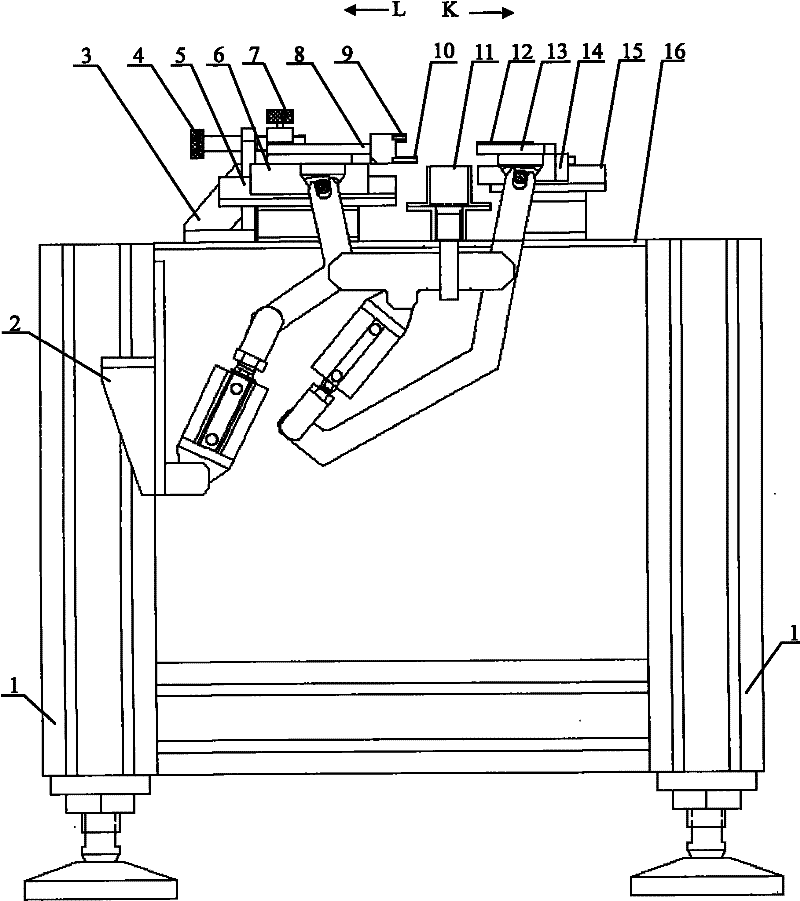
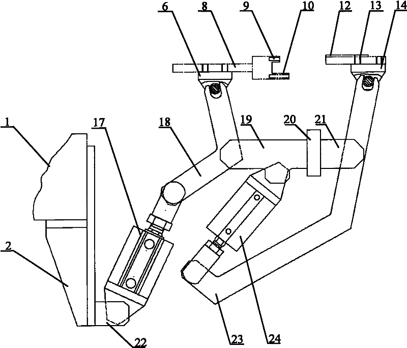
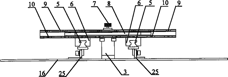
[0025] After the test starts, place the lighter to be tested in the material box 11. The gasket can be replaced in the material box to realize the compatibility of different models of lighters in the clamping process; the number of V-shaped ports is determined according to the number of tested lighters; pneumatic The large cylinder 17 and the small cylinder 24 in the mechanism use compressed air as the power source to control the short swing rod 18 installed on the left slider 6 of the actuator to slide along the direction of the left guide rail 5, and to control the installation on the right slider 14. The long swing rod 23 slides along the right guide rail 15 to realize the movement of the positioning plywood and the clamping plywood 13 toward or away from the lighter to be tested; a limit pull rod 4 is installed on one side of the positioning mechanism, and the left slider 6 follows When the left guide rail 5 moves to the left side of the base plate 16, when the action rod 26...


PUM


Abstract

The present invention discloses a pneumatic holding device of a lighter, comprising a door-shaped frame, a pneumatic mechanism, a positioning clamping plate mechanism and a holding clamping plate mechanism, wherein the positioning clamping plate mechanism and the holding clamping plate mechanism are respectively arranged at the left side and the right side of a substrate at the upper end of the door-shaped frame; a lighter material box is arranged on the substrate at the upper end of the door-shaped frame between the positioning clamping plate mechanism and the holding plate clamping mechanism; and the pneumatic mechanism is arranged below the substrate of the door-shaped frame. In the invention, the pneumatic mechanism is adopted and has simple structure and convenient use, and a working medium is inexhaustible air having no pollution, low cost and simple exhaust-gas disposal. Compared with a hydraulic mode, the pneumatic mode can be used at high-temperature occasions. In the positioning clamping plate mechanism, an upper clamping plate and a lower clamping plate are adopted, and the holding clamping plate is matched so as to ensure that the lighter is at a vertical gesture all the time, which is beneficial to improving the subsequent detection precision.

Description

Technical field [0001] The invention relates to a pneumatic clamping device, in particular to a pneumatic clamping device for a lighter. Background technique [0002] In the production of lighters, testing the various parameters of the lighter is a very important link. To achieve high-precision detection, the lighter must be positioned efficiently and accurately. Existing lighter quality inspections are mostly manual inspection methods. Workers hold lighters, observe the height of the flame, feel the pressure, and so on. This method has great subjective factors and insufficient labor intensity. Summary of the invention [0003] In view of the shortcomings of the detection device in the above-mentioned background art, the purpose of the present invention is to provide a pneumatic clamping device for a lighter. [0004] The technical scheme adopted by the present invention is: [0005] Including portal frame, pneumatic mechanism, positioning plywood mechanism and clamping plywood mec...

Claims


Application Information

Patent Timeline
Patent Type & Authority Patents(China)
IPC IPC(8): F23Q23/00
Inventor 叶树亮杨遂军侯德鑫
Owner HANGZHOU YOUNG INSTR SCI & TECH
Learn More