

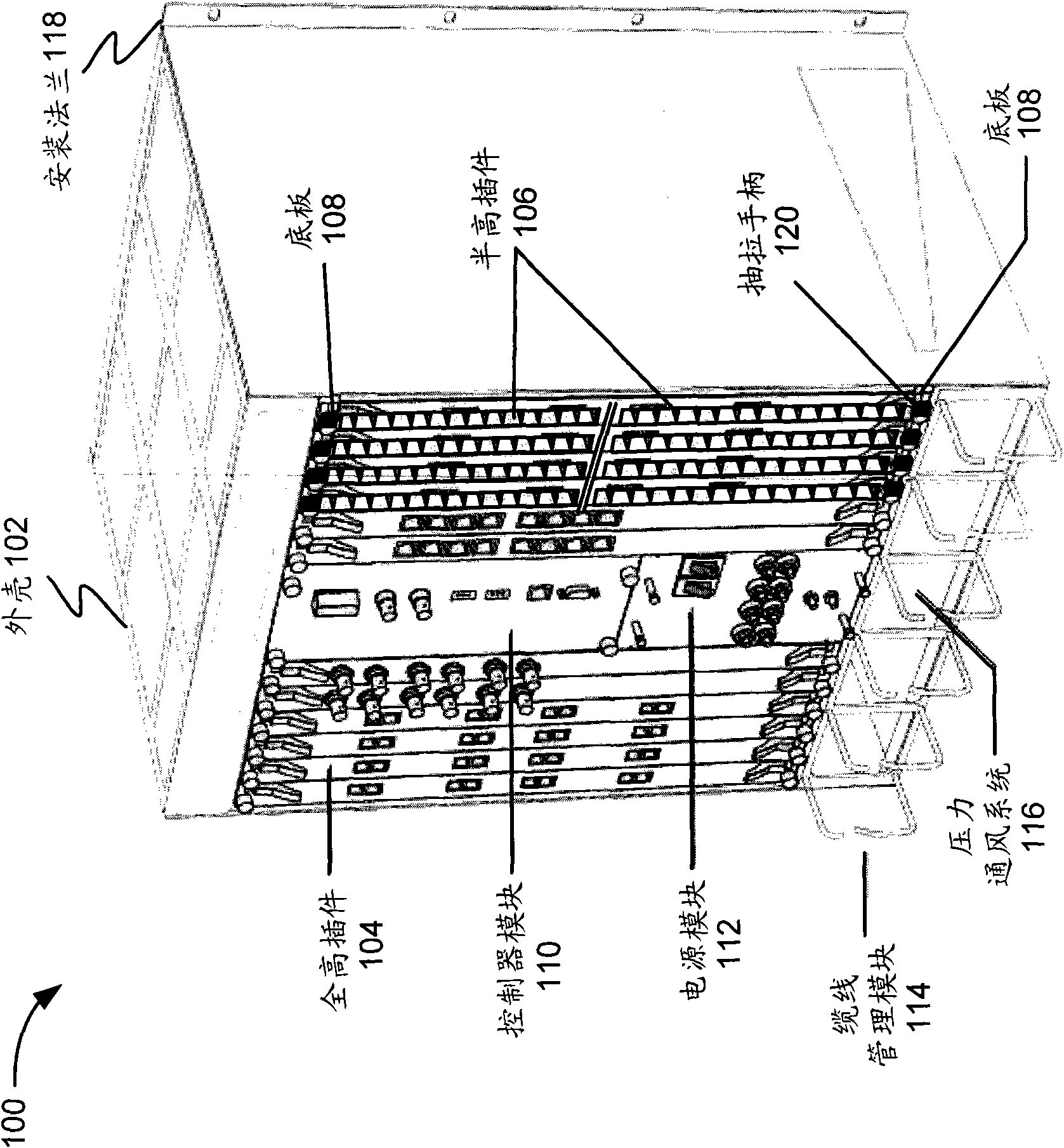
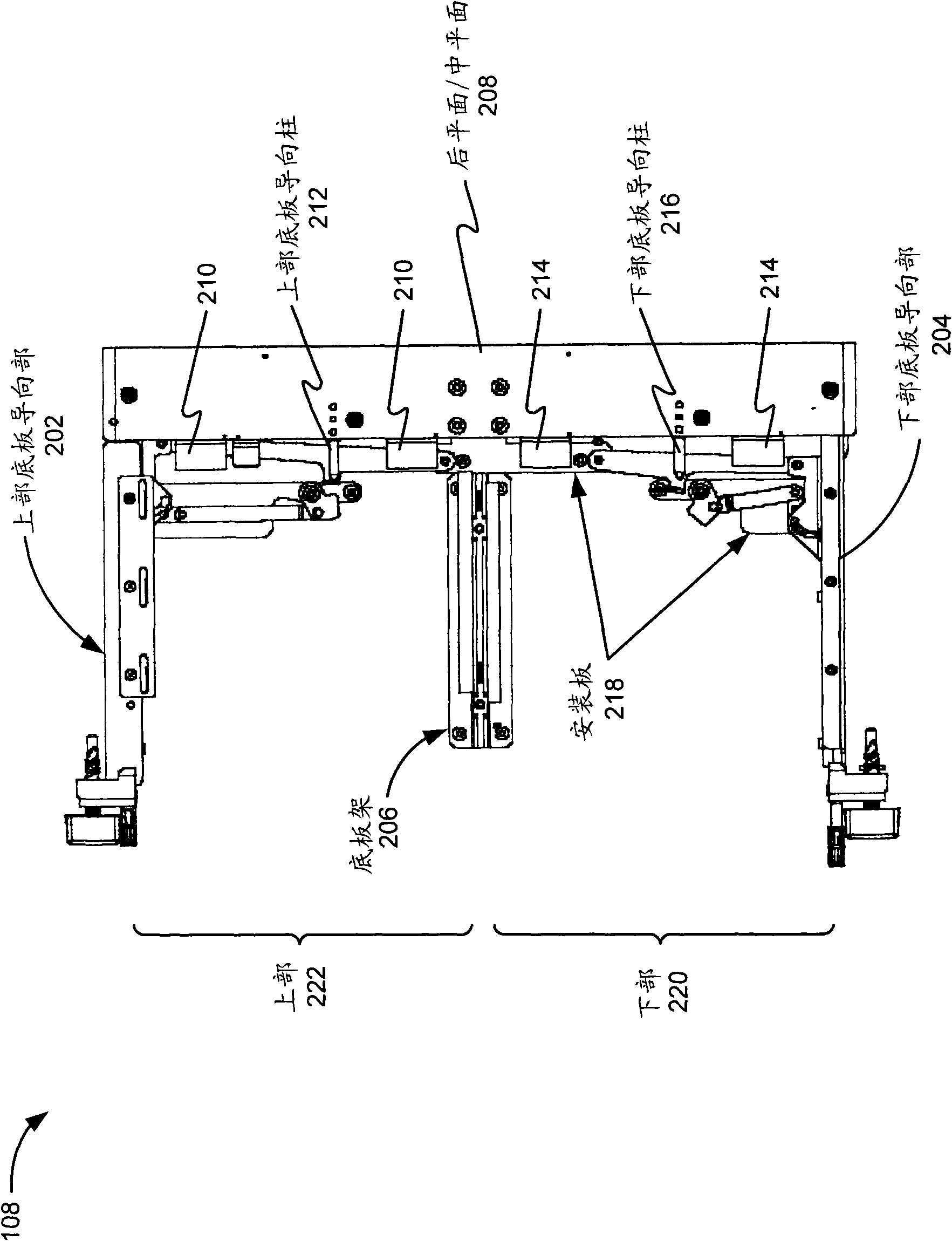
Retention-extraction device for removable cards in a chassis
A technology for extracting devices and bottom plates, applied in the direction of clamping/extracting devices, coupling devices, parts of connecting devices, etc., can solve the problem of small space, hindering the removal of detachable plug-ins, bottom plate slots and/or detachable plug-ins space constraints etc.
- Summary
- Abstract
- Description
- Claims
- Application Information
AI Technical Summary
Problems solved by technology
Method used
Image

Examples
example
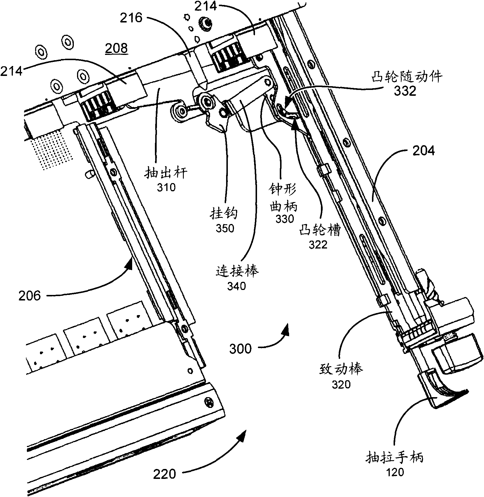
[0051] combined reference Figures 3A-3C and Figure 4 In operation, insertion of the card 400 may cause a portion of the card 400 (such as the protrusion 422 ) to contact the protrusion 316 on the extraction lever 310 as the mating connector 410 of the card 400 engages the lower chassis connector 214 . During insertion of insert 400 , force applied to protrusion 316 by nub 422 may cause the outboard end of extraction rod 310 to rotate in a counterclockwise direction (eg, toward posterior / midplane 208 ). Counterclockwise movement of the outboard end of the extraction rod 310 may cause the actuation bar 320 to slide forwardly toward the posterior / midplane 208 along with the cam slot 322 . Forward movement of the actuator rod 320 and the cam slot 322 can cause the cam follower 332 to rotate the bell crank 330 . Such as Figure 3B As shown, bell crank 330 is rotatable in a counterclockwise direction, thereby causing connecting rod 340 to impart rotational motion to hook 350 . ...
PUM
 Abstract
Description
Claims
Application Information