Pneumatic tire

A technology for pneumatic tires and tires, which is applied in the direction of pneumatic tires, tire parts, tire treads/tread patterns, etc. It can solve the problems of increasing the volume and the inability to fully increase the total groove length, etc., and achieve the purpose of improving the sound absorption effect Effect

Inactive Publication Date: 2010-08-11
BRIDGESTONE CORP
View PDF4 Cites 10 Cited by
  • Summary
  • Abstract
  • Description
  • Claims
  • Application Information

AI Technical Summary

Problems solved by technology

[0004] As described in the above-mentioned prior art, when the transverse groove has a structure with two wing-shaped grooves, the length of the noise-absorbing groove is the distance from the front end of the longer one of the two wing-shaped grooves, and the shorter one follows. To increase the volume, therefore, there is a problem that the total groove length cannot be sufficiently increased

Method used


Image

  • Pneumatic tire
  • Pneumatic tire
  • Pneumatic tire

Examples


Embodiment approach 1

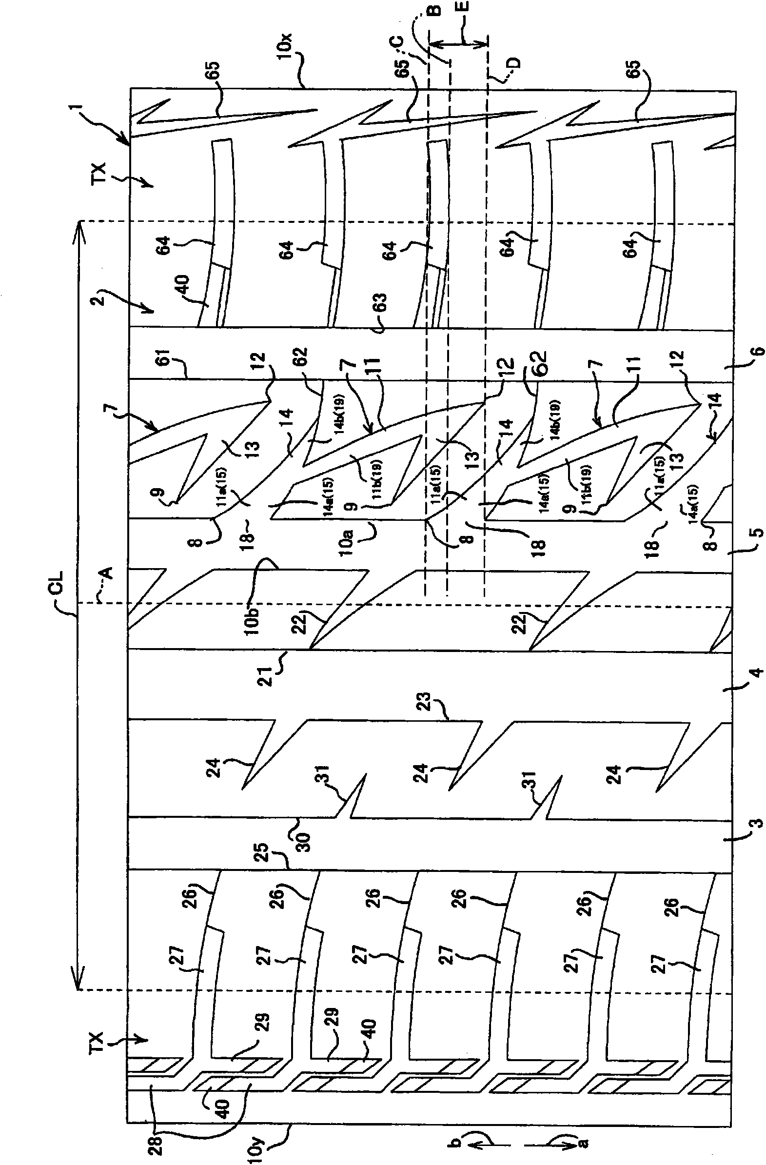
[0029] figure 1 with Figure 5 Indicates Embodiment 1, figure 1 Indicates the groove structure (tread pattern) of the tire contact surface of the pneumatic tire, Figure 5 Indicates the relationship between the turn-back ditch of the horizontal ditch and the other side ditch.

[0030] Such as figure 1 As shown, the tire contact surface (tread portion) 2 of the pneumatic tire 1 (hereinafter simply referred to as the tire 1) has a plurality of circumferential grooves 3, 4, 5, 6 and a plurality of lateral grooves 7, 7 . . . . Each of the circumferential grooves 3 , 4 , 5 , 6 is formed continuously in one circle along the circumferential direction of the tire contact surface 2 . The plurality of lateral grooves 7 are formed extending from one circumferential groove 5 formed at a position closest to the equatorial plane A of the tire 1 . The circumferential groove 5 is formed at a position deviated from the equatorial plane A of the tire 1 toward the one side edge 10x side of ...

Embodiment approach 2

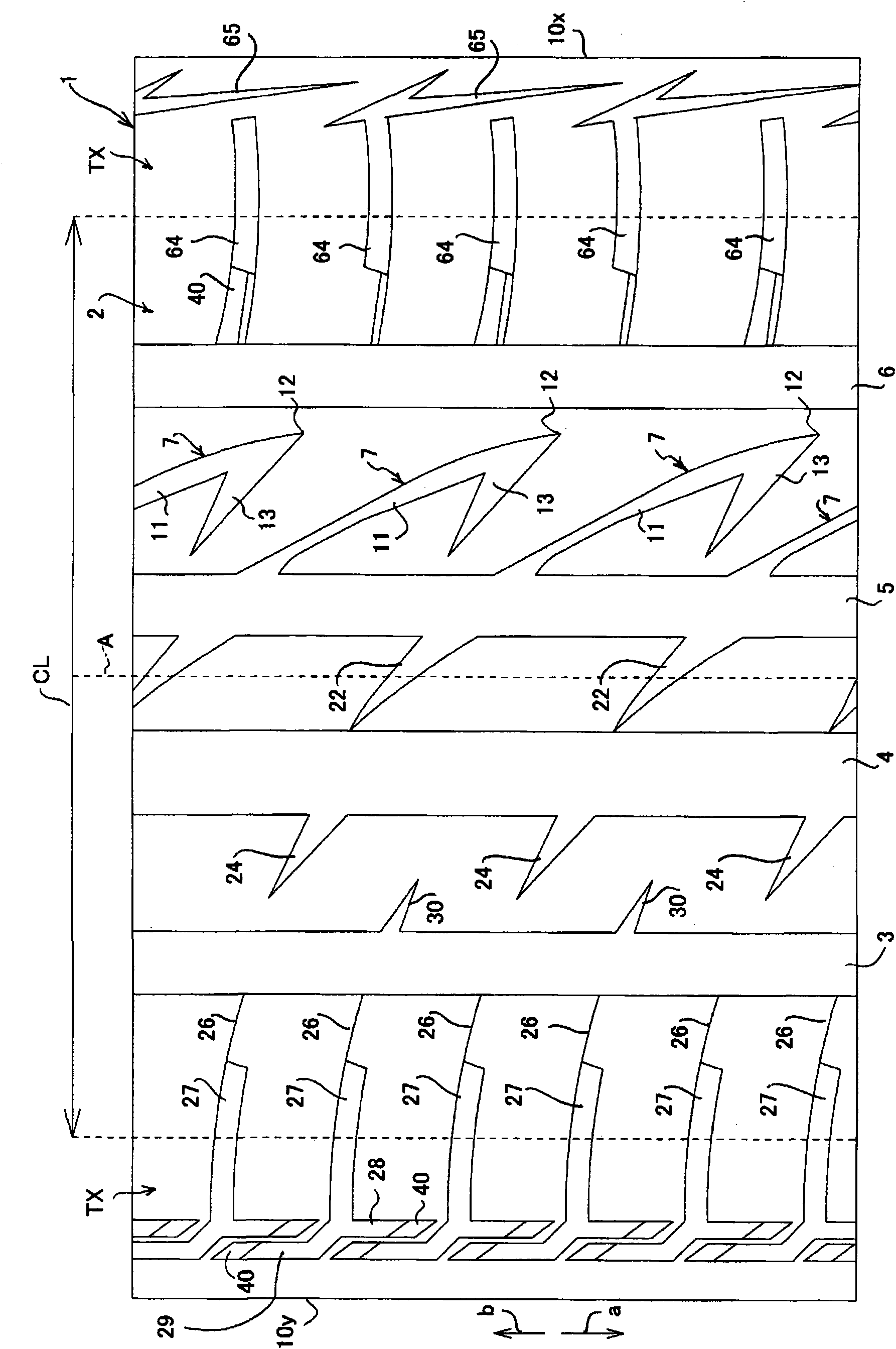
[0048] Such as figure 2 As shown, the lateral groove 7 is formed by the one-way groove 11 and the return groove 13, and other structures may be the pneumatic tire 1 having the tire contact patch 2 formed in the same manner as in the first embodiment.

[0049] According to Embodiment 2, since the lateral groove 7 is formed of the one-way groove 11 and the folded groove 13, the total length of the grooves responsible for the sound absorbing effect can be ensured, and thus the sound absorbing effect can be enhanced by the lateral groove 7. In the case of Embodiment 2, by setting the extension length of the one-way groove 11 to 9 cm and the extension length of the return groove 13 to 4 cm, the total length of the grooves bearing the sound-absorbing effect can be ensured to be relatively long. Compared with the case of the directional groove 11, the effect of absorbing lower frequency sound can be obtained.

Embodiment approach 3

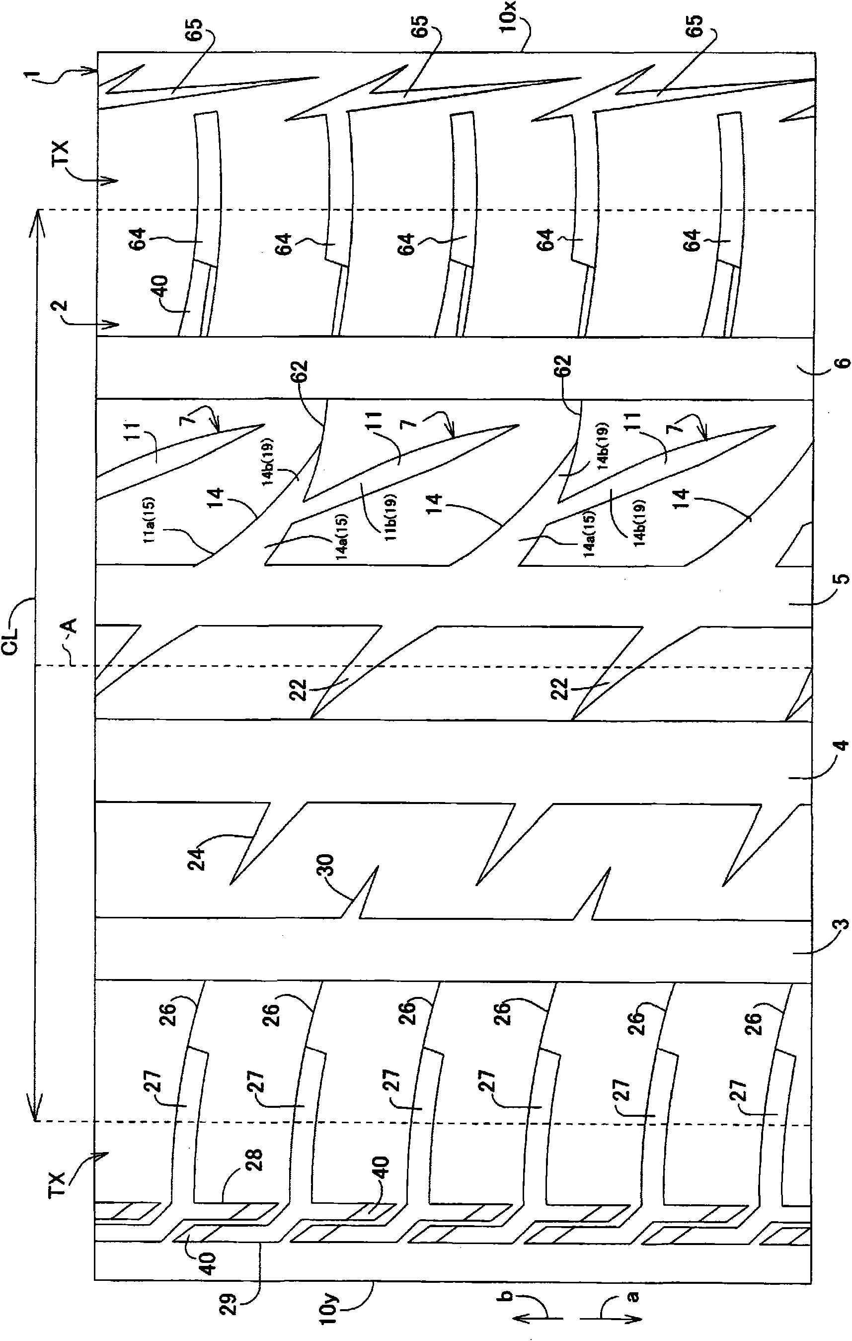
[0051] Such as image 3 As shown, the lateral groove 7 is formed of one directional groove 11 and the other directional groove 14 , and other structures may be the pneumatic tire 1 having the tire contact patch 2 formed in the same manner as in the first embodiment.

[0052] According to Embodiment 3, since the lateral groove 7 is formed by the one direction groove 11 and the other direction groove 14, the one direction groove 11 having a longer groove length bears the effect of absorbing the sound of a specific frequency, and the other direction groove 14 uses the other direction groove. The volume increases the total groove volume of the lateral grooves 7, and therefore, the sound absorbing effect by the lateral grooves 7 can be enhanced. In the case of Embodiment 3, by making the extending length of the one-directional groove 11 9 cm and the extending length of the other-directional groove 14 4 cm, the total groove volume is increased compared to the case where only the one...


PUM


Abstract

A pneumatic tire having lateral grooves that improve a sound absorption effect. The pneumatic tire has on its tread surface (2) a circumferential groove continuously circumferentially formed in the tread surface (2) and also has lateral grooves extended from the circumferential groove. The lateral grooves are each formed such that one end of the lateral groove is connected to the circumferential groove and the other end is a dead end. Each lateral groove has one groove (11) extending in one direction from the circumferential groove (5) toward a side edge of the tire, and also has the other groove (14) extending in the other direction from the circumferential groove (5) toward the side edge of the tire. A root section (11a), which is close to the circumferential groove (5), of the one groove (11) and a root section (14a), which is close to the circumferential groove (5), of the other groove (14) are constructed from a common groove (15). The front end (11b) of the one groove (11) and the front end (14b) of the other groove (14) are constructed from grooves (19) branched from the front end of the common groove (15).

Description

technical field [0001] The present invention relates to a groove structure formed on a tire contact patch of a pneumatic tire. Background technique [0002] There is known a pneumatic tire which has a circumferential groove formed continuously along the circumference of the tire contact surface on the tire contact surface and a transverse groove extending from the circumferential groove, one end of the transverse groove is connected to the circumferential groove, The other end is closed (for example, refer to Patent Document 1, etc.). The structure of the above-mentioned lateral groove has a one-directional groove extending in one direction from the circumferential groove to the tire side edge, and two directions extending from the front end of the one-directional groove to the circumferential direction of the tire ground contact surface in one direction and the other direction. Winged grooves. [0003] Patent Document 1: Japanese Patent Laid-Open No. 2006-69305 [0004] ...

Claims


Application Information

Patent Timeline
Patent Type & Authority Applications(China)
IPC IPC(8): B60C11/04B60C5/00B60C11/13
CPCB60C2011/0383B60C11/0304B60C2011/0388B60C2011/0381B60C11/1323B60C11/0306B60C2011/0374
Inventor 岩渕聪太郎
Owner BRIDGESTONE CORP
Why Eureka
Try Eureka