
Seat slide device for vehicle

A sliding device, vehicle technology, applied in vehicle seats, special positions of vehicles, movable seats, etc., can solve problems such as weight increase, and achieve the effect of ensuring strength and avoiding large-scale

Inactive Publication Date: 2010-08-11
AISIN SEIKI KK
View PDF2 Cites 12 Cited by
  • Summary
  • Abstract
  • Description
  • Claims
  • Application Information

AI Technical Summary

Problems solved by technology

Therefore, in order to prevent the peeling of the upper rail 102 relative to the lower rail 101, the lower hooks 104a, 104b and the upper hooks 105a, 106a must be sufficiently thick, resulting in an increase in weight.

Method used


Image

  • Seat slide device for vehicle
  • Seat slide device for vehicle
  • Seat slide device for vehicle

Examples


Embodiment Construction

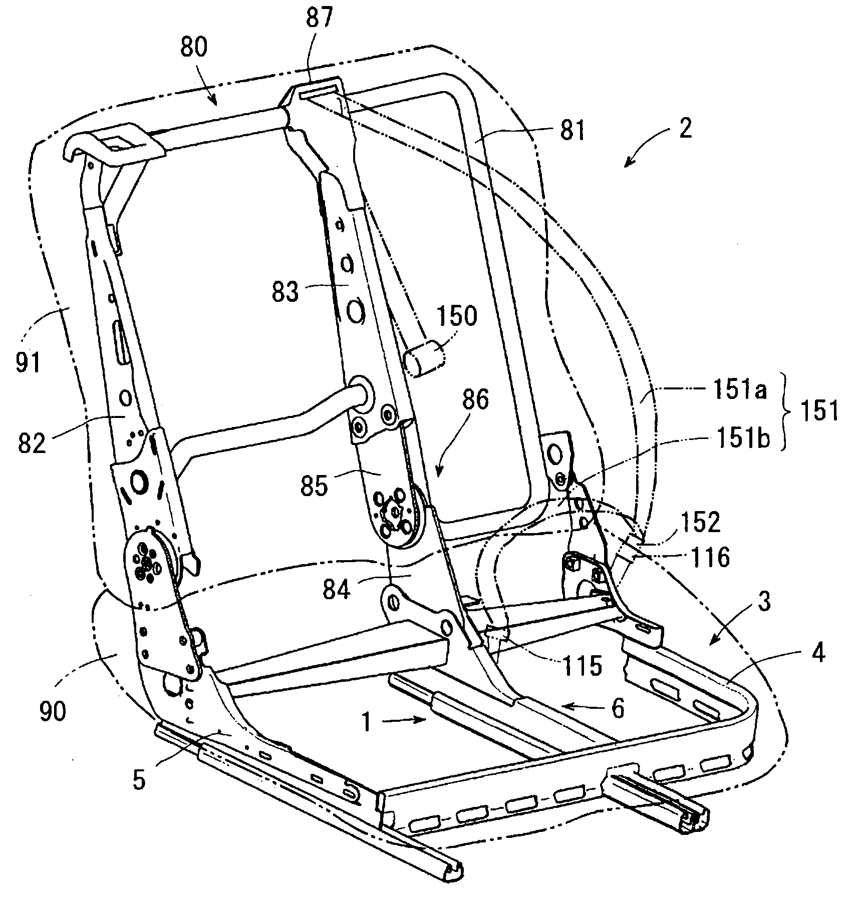
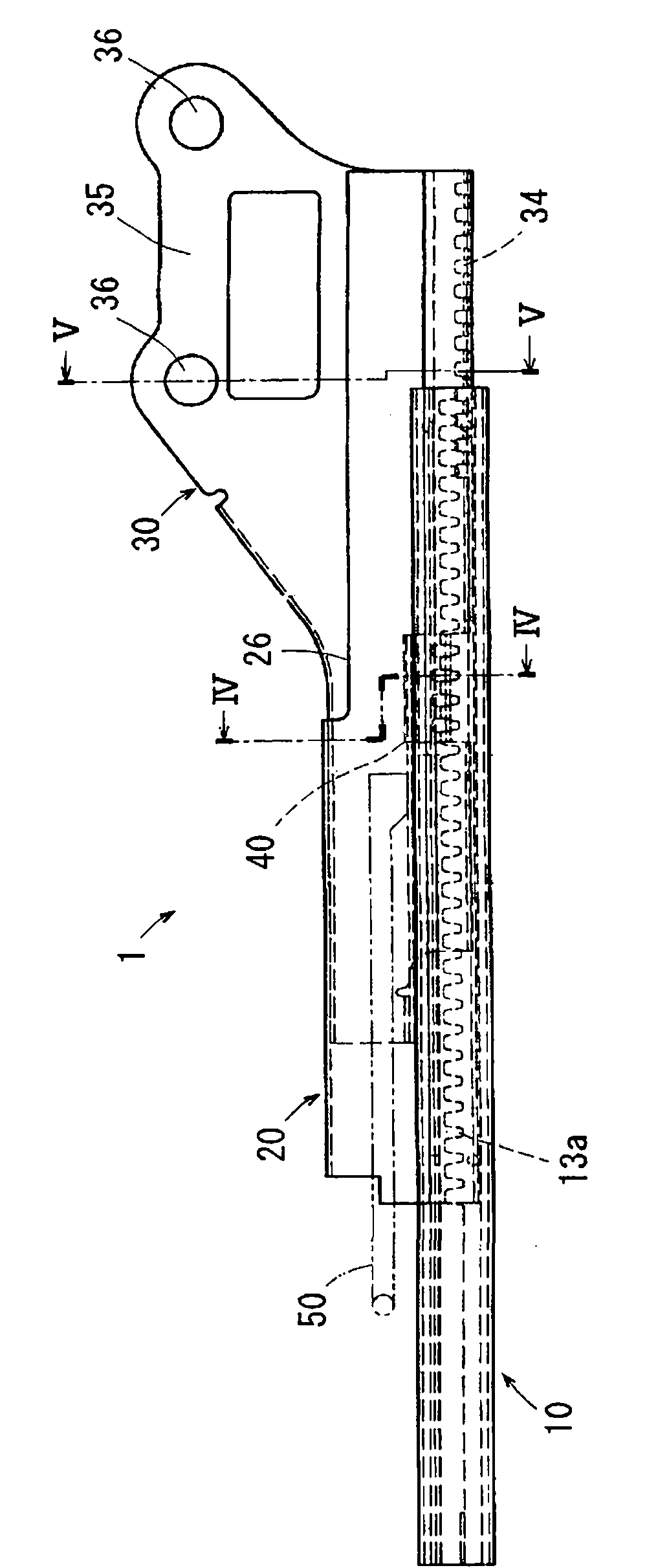
[0029] Hereinafter, an embodiment in which the vehicle seat sliding device according to the present invention is embodied as a vehicle seat device will be described based on the drawings. Such as figure 1 As shown, in this vehicle seat device, a vehicle seat frame 2 is attached to a vehicle seat sliding device 1 . The vehicle seat frame 2 includes: a seat cushion frame 3 supporting a seat cushion 90; a seat back frame 80 supporting a seat back 91; The recliner 86 and the shoulder belt fixing device 87 are arranged on the upper end of the seat back frame 80 . Backrest side frames 81 and 82 are arranged on both sides of the seat back frame 80 , and a hollow back center frame 83 formed in the shape of a square column is arranged in the center thereof. In addition, cushion side frames 4 and 5 are disposed on both sides of the cushion frame 3 , and a cushion center frame 6 is disposed at the center thereof. An upper arm 85 made of a thick plate is bolted to the lower portion of...


PUM


Abstract

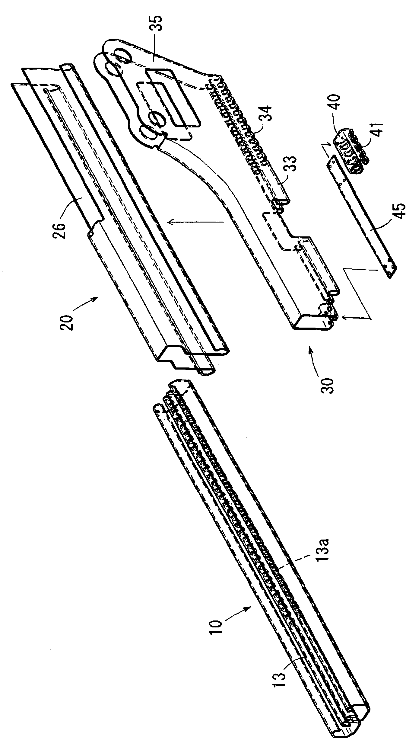
A seat slide device for a vehicle is small-sized and light-weighted and has assured strength. A lower rail (10) has a base section (11) extending facing the floor of the vehicle, two sheets of first inner sections (12) extending upward from the center of the base section (11) while being in close contact with each other, and reverse U-shaped lower hook sections (13) extending outward from the upper ends of the first inner sections (12). An upper rail (20) has a horizontal wall section (21) horizontal to the base section (11) and also has vertical wall sections (22) extending downward from opposite ends of the horizontal wall section (21). Installed in the upper rail (20) are joined sections (32) and hook members (30). The joined sections (32) are joined to the vertical wall sections (22) and extend downward. The hook members (30) have U-shaped upper hook sections (33) extending inward from the lower ends of the joined sections (32). When a load separating the lower rail (10) from the upper rail (20) is applied to the upper rail, the lower hook sections (13) and the upper hook sections (33) are engaged with each other.

Description

technical field [0001] The present invention relates to a seat slide device for a vehicle, which includes a lower rail fixed to a floor of a vehicle, an upper rail supported so as to be movable relative to the lower rail, and a lock mechanism for absorbing a peeling load of the upper rail relative to the lower rail. Background technique [0002] It was previously known that there is a Figure 7 A vehicle seat device using the vehicle seat sliding device 100 is shown. In this vehicle seat device, a vehicle seat frame 109 is attached to a vehicle seat slide device 100 . The vehicle seat frame 109 includes: a seat cushion frame 110 supporting the seat cushion 90; a seat back frame 120 supporting the seat back 91; The recliner 140 and the shoulder belt fixing device 130 are arranged on the upper end of the seat back frame 120 . Back side frames 121 and 122 are arranged on both sides of the seat back frame 120 , and a hollow back center frame 123 formed in the shape of a square...

Claims


Application Information

Patent Timeline
Patent Type & Authority Applications(China)
IPC IPC(8): B60N2/06B60N2/42
CPCB60N2/0818B60N2/0875B60N2/688B60N2/0705B60N2/072B60N2/073
Inventor 山田幸史冈崎裕行后藤直希
Owner AISIN SEIKI KK
Learn More