
Delaminating mechanical adjustment device

A mechanical adjustment and working layer technology, applied in the direction of identification devices, instruments, etc., can solve problems such as lack of stability, image destruction, loosening or springback of plastic parts, and achieve increased flexibility and stability, firmness and durability , the effect of increased operational accuracy

Inactive Publication Date: 2010-08-18
巨洋神州科技集团有限公司
View PDF0 Cites 1 Cited by
  • Summary
  • Abstract
  • Description
  • Claims
  • Application Information

AI Technical Summary

Problems solved by technology

Because these driving actions have undergone multiple transmissions and angle changes, and different actions will have an impact, or even linkage, the operation process is complicated and difficult to distinguish. It is not a purely one-axis division, which causes inconvenience to the staff.
And because some precision parts are too complex and fragile, a little improper operation may cause damage to the parts, leading to the scrapping of the whole set of devices, which will cause great inconvenience to the work
This kind of multi-axis adjustment frame also lacks stability. The metal shrapnel and plastic parts inside the device will loosen or rebound after a long time, which will cause the image that has been adjusted to be destroyed, resulting in repeated labor for the staff. Reduced work efficiency

Method used


Image

  • Delaminating mechanical adjustment device
  • Delaminating mechanical adjustment device
  • Delaminating mechanical adjustment device

Examples


Embodiment Construction

[0026] The present invention will be further described below in conjunction with accompanying drawing and example.

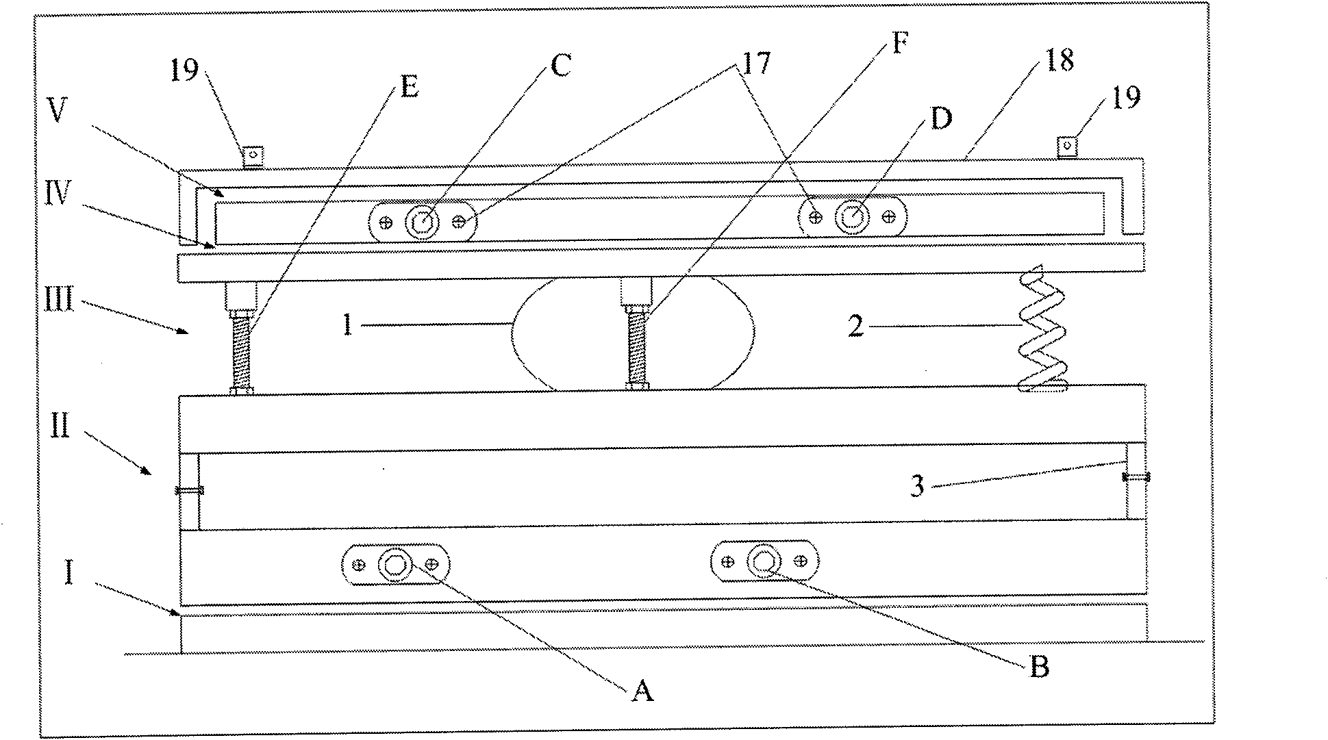
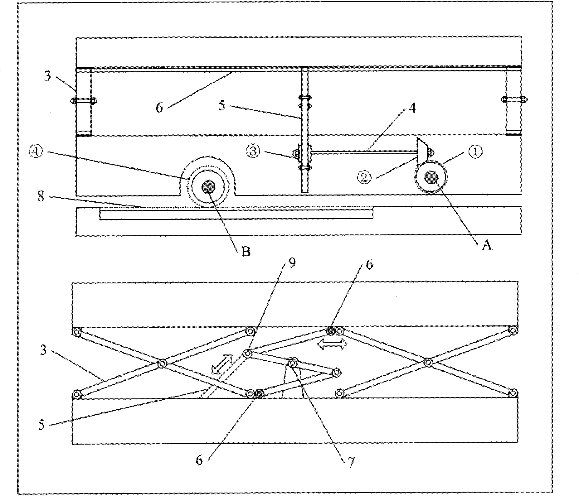
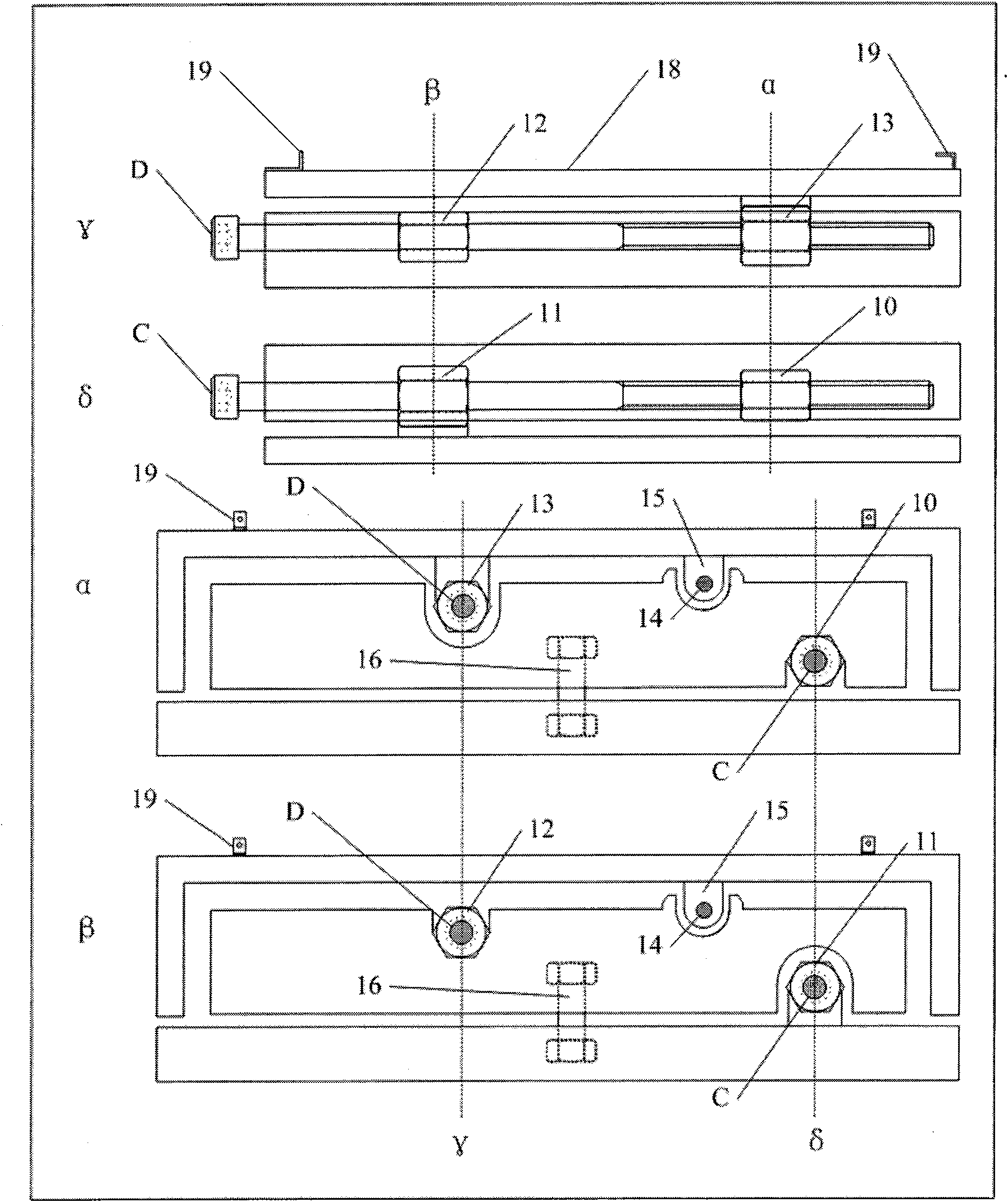
[0027] Such as figure 1 As shown, the reflection adjusting device of the present invention is divided into five working layers I, II, III, IV and V from bottom to top. The first layer is responsible for adjusting the horizontal displacement, which is executed by the B axis; the second layer is responsible for adjusting the zoom in and out, and is executed by the A axis; the third layer is responsible for adjusting the left and right trapezoid and the up and down trapezoid, and is executed by the E-pillar and F-pillar; the fourth layer is responsible for adjustment Image rotation is performed by the C axis; the fifth layer is responsible for adjusting the vertical displacement and is performed by the D axis. There is a locking bolt next to the operating end of each axis to lock the axis. After locking, the axis will not change due to factors such as long-term vi...


PUM


Abstract

The invention provides a delaminating mechanical adjustment device which comprises five upper and lower working layers and six drive rods with four shafts and two columns, wherein the five working layers are sequentially a horizontal displacement layer I, a scaling layer II, a trapezoidal layer III, a rotating layer IV and a vertical displacement layer V from bottom to top and respectively realize six actions of horizontal displacement, scaling, horizon, vertical trapezoid, rotation and vertical displacement of an image; and the six drive rods are respectively in charge of an action. The delaminating mechanical adjustment device is characterized in that all actions are finished in respective working layer without referring to other working layers; all the drive rods perform self functions without mutual interference, and each drive rod is provided with a locking bolt; and the image action driven by the drive rods can not generate after locking. The invention provides a calender base adjustment device with flexible operation, accurate positioning, duration and stability for a user.

Description

technical field [0001] The invention relates to the field of large-screen splicing display systems, in particular to a display unit box applied to the large-screen splicing system. Background technique [0002] With the development of science and technology, in recent years, the technology of large-screen splicing display systems has become more and more perfect, and gradually formed its own set of mature theories and operating specifications. Among them, in terms of physical adjustment of optical images, a set of more than one The shaft adjustment frame is used as the adjustment method of the optomechanical base. According to their different ideas, the producers of multi-axis adjustment mounts have different working processes, but they all have one thing in common: complex structure, difficult operation, fragile parts, and poor stability. [0003] In the display unit box, the function of the multi-axis adjustment frame is to provide a mounting base for the optical machine,...

Claims


Application Information

Patent Timeline
Patent Type & Authority Applications(China)
IPC IPC(8): G09F9/00
Inventor 韩福涛赵亮
Owner 巨洋神州科技集团有限公司
Learn More