A Permanent Magnet DC Brushed Motor

A brushed motor and permanent magnet DC technology, which is applied in the field of PMDC motors and multi-pole PMDC motors, can solve the problems of small motor commutator diameter and increase the difficulty of commutator manufacturing, so as to reduce the number of commutator pieces and simplify processing , the effect of making full use of

Inactive Publication Date: 2016-05-25
JOHNSON ELECTRIC SHENZHEN
View PDF5 Cites 0 Cited by
  • Summary
  • Abstract
  • Description
  • Claims
  • Application Information

AI Technical Summary

Problems solved by technology

[0006] The defect of the above-mentioned existing PMDC motor is that in some application fields, especially the field of micro-motors for automobiles, due to space constraints, the diameter of the motor commutator is usually relatively small
Under the condition that the diameter of the commutator remains unchanged, if a pole-slot fit with a large number of slots is used, it will increase the difficulty of manufacturing the commutator; brush width, which also causes a lot of adverse effects

Method used


Image

  • A Permanent Magnet DC Brushed Motor
  • A Permanent Magnet DC Brushed Motor
  • A Permanent Magnet DC Brushed Motor

Examples


no. 1 example

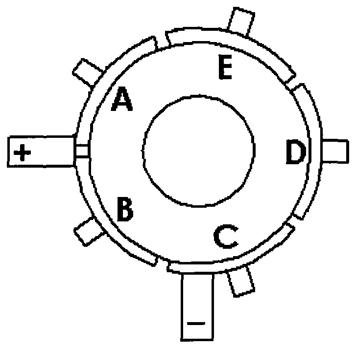
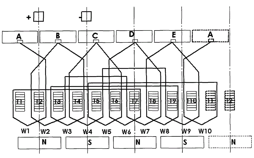
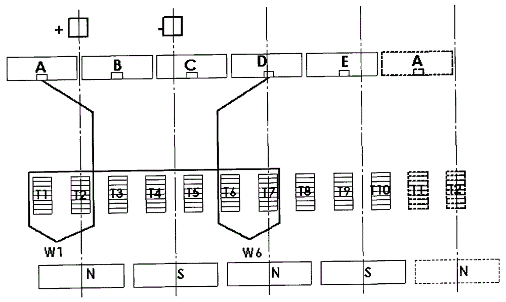
[0027] figure 1 It is a schematic diagram of the positional relationship between the carbon brushes and the commutator of the PMDC motor with 4 poles, 10 slots and 5 commutator segments according to the first embodiment of the present invention. Such as figure 1 As shown, the motor uses two carbon brushes in frictional contact with the commutator. The two carbon brushes are separated by an electrical angle of 180° in the direction of the outer circumference of the commutator, and the corresponding mechanical angle is about 90°. The commutator includes 5 commutator segments, that is, the number of commutator segments is equal to half of the number of slots. For the convenience of description, these 5 commutator segments are sequentially marked as commutator segments A~E along the circumferential direction of the commutator , two adjacent commutator segments are separated by an electrical angle of 144° along the outer circumference of the commutator, and the corresponding mecha...

no. 2 example

[0036] Figure 6 It is a schematic diagram of the positional relationship between the carbon brushes and the commutator of a PMDC motor with 4 poles, 14 slots and 7 commutator segments according to the second embodiment of the present invention. Such as Figure 6 As shown, the motor uses two carbon brushes in frictional contact with the commutator. The two carbon brushes are separated by an electrical angle of about 180° in the direction of the outer circumference of the commutator, and the corresponding mechanical angle is about 90°. The commutator includes 7 commutator segments, that is, the number of commutator segments is equal to half of the number of slots. For the convenience of description, these 7 commutator segments are sequentially marked as commutator segments A to G along the circumferential direction of the commutator.

[0037] Figure 7 for Figure 6 The schematic diagram of the winding connection of the PMDC motor is shown. It is assumed that the winding is ...

no. 3 example

[0040] Figure 8 It is a schematic diagram of the positional relationship between the carbon brushes and the commutator of the PMDC motor with 8 poles, 18 slots and 9 commutator segments according to the third embodiment of the present invention. Such as Figure 8 As shown, the motor uses two carbon brushes in frictional contact with the commutator. The two carbon brushes are separated by an electrical angle of 540° in the circumferential direction of the commutator, and the corresponding mechanical angle is 135°. The commutator includes 9 commutator segments, that is, the number of commutator segments is equal to half of the number of slots. For the convenience of description, these 9 commutator segments are sequentially marked as commutator segments A~I along the circumferential direction of the commutator .

[0041] Figure 9 for Figure 8 The schematic diagram of the winding connection of the PMDC motor is shown. It is assumed that the winding is cut from the center li...


PUM


Abstract

The invention provides a permanent-magnet DC brush motor which comprises a stator and a rotor. The rotor comprises a rotating shaft (31), a rotor iron core (32) and a commutator (33) which are fixed to the rotating shaft, and a winding wound on the teeth of the rotor iron core (32), wherein the number of the commutator segments of the commutator (33) are less than that of the teeth of the rotor iron core (32); the winding comprises a plurality of element groups; each element group comprises at least two elements which are directly connected in series; the two elements respectively arranged at the head and the tail of each element group are directly connected to the commutator segments; and each element group is only directly connected with two commutator segments. The permanent-magnet DC brush motor has the beneficial effects that each element group comprises at least two elements which are directly connected in series and each element group is only directly connected with two commutator segments, so the number of the commutator segments is reduced and thereby the commutator is easier to manufacture, which is particularly favorable for the occasion in which the diameter of the commutator is small. Furthermore, no equalizer lead is necessary to be arranged on the commutator when the permanent-magnet DC brush motor is implemented.

Description

technical field [0001] The present invention relates to a permanent magnet brushed direct current (PMDC) motor, and more particularly to a multi-pole PMDC motor. The term "multi-pole" used herein means a motor with four or more stator poles. The invention is particularly suitable for PMDC motors with four or eight stator poles. Background technique [0002] Figure 10 shows a widely used PMDC motor. The motor includes a stator and a rotor. The stator includes a casing 21 , a permanent magnet pole 22 installed inside the casing, and end caps 23 and 24 installed at both ends of the casing. The rotor is installed in the stator and can rotate relative to the stator. The rotor includes a rotating shaft 31, a rotor core 32, a commutator 33 and a winding (not shown in the figure), wherein the rotor core 32 and the commutator 33 are fixed to the rotating shaft 31 Above, the rotor core 32 has several teeth 34 forming salient poles, and windings are wound on the teeth and are electri...

Claims


Application Information

Patent Timeline
IPC IPC(8): H02K23/04H02K23/26H02K1/17
Inventor 秦锐锋杜成顺梁吉玉刘飞
Owner JOHNSON ELECTRIC SHENZHEN
Why Eureka
Try Eureka