Pump, particularly for a hydraulic unit of an electronically controlled vehicle brake unit

A technology of automobile braking system and hydraulic device, applied in the field of pump of hydraulic device, can solve the problems of flushing and bearing wear increase, and achieve the effect of enlarging the eccentric cavity

Active Publication Date: 2010-08-18
ROBERT BOSCH GMBH
View PDF0 Cites 4 Cited by
  • Summary
  • Abstract
  • Description
  • Claims
  • Application Information

AI Technical Summary

Problems solved by technology

Penetration of brake fluid into eccentric bearings and / or drive bearings can lead to grease being washed out and thus increased bearing wear

Method used


Image

  • Pump, particularly for a hydraulic unit of an electronically controlled vehicle brake unit
  • Pump, particularly for a hydraulic unit of an electronically controlled vehicle brake unit
  • Pump, particularly for a hydraulic unit of an electronically controlled vehicle brake unit

Examples


Embodiment Construction

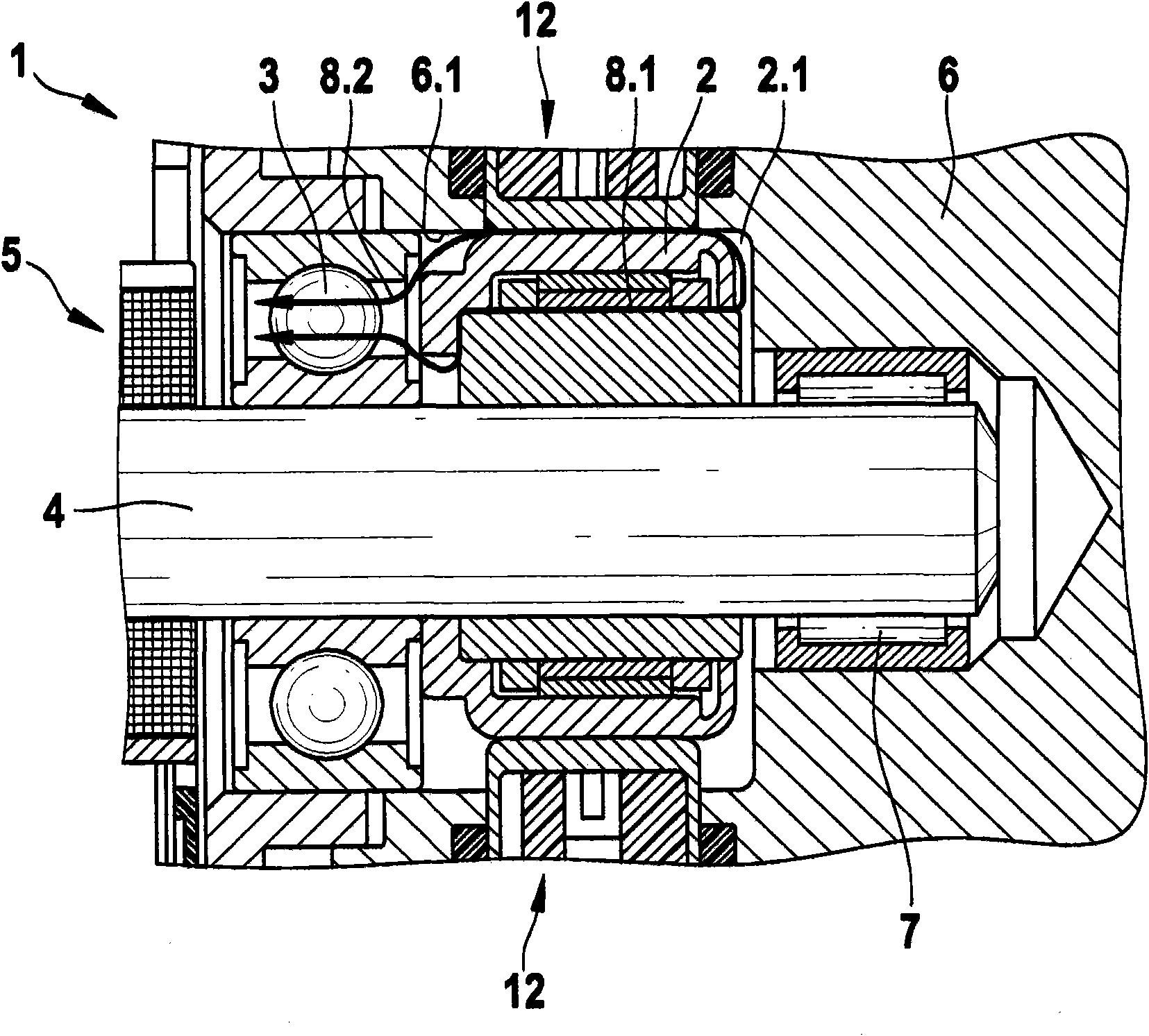
[0014] A conventional pump without compensation is shown in FIG. 1 . It can be seen that this conventional pump 1 comprises an eccentric bearing 2, a drive bearing 3, a drive shaft 4, a drive motor 5, a pump housing 6 with a motor bore 6.1 and a drive shaft bearing 7. The leakage paths of the pressure medium mentioned at the outset are indicated by arrows 8.1 and 8.2.

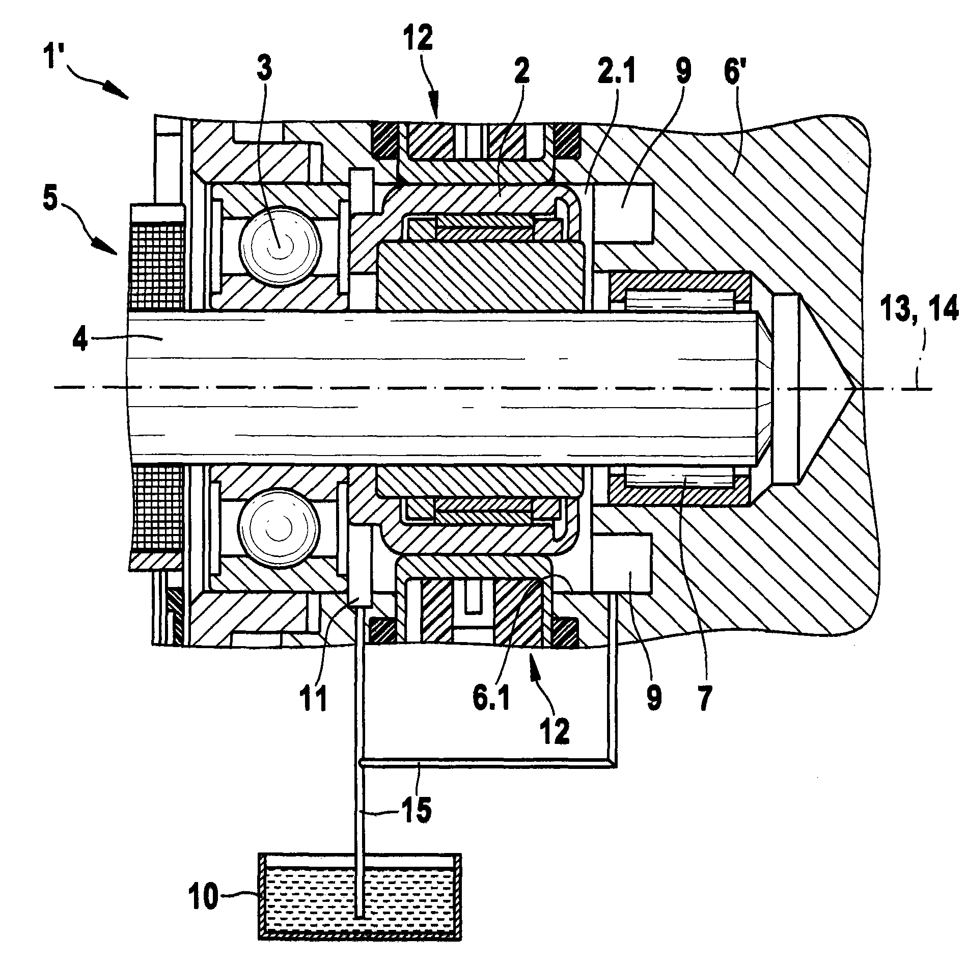
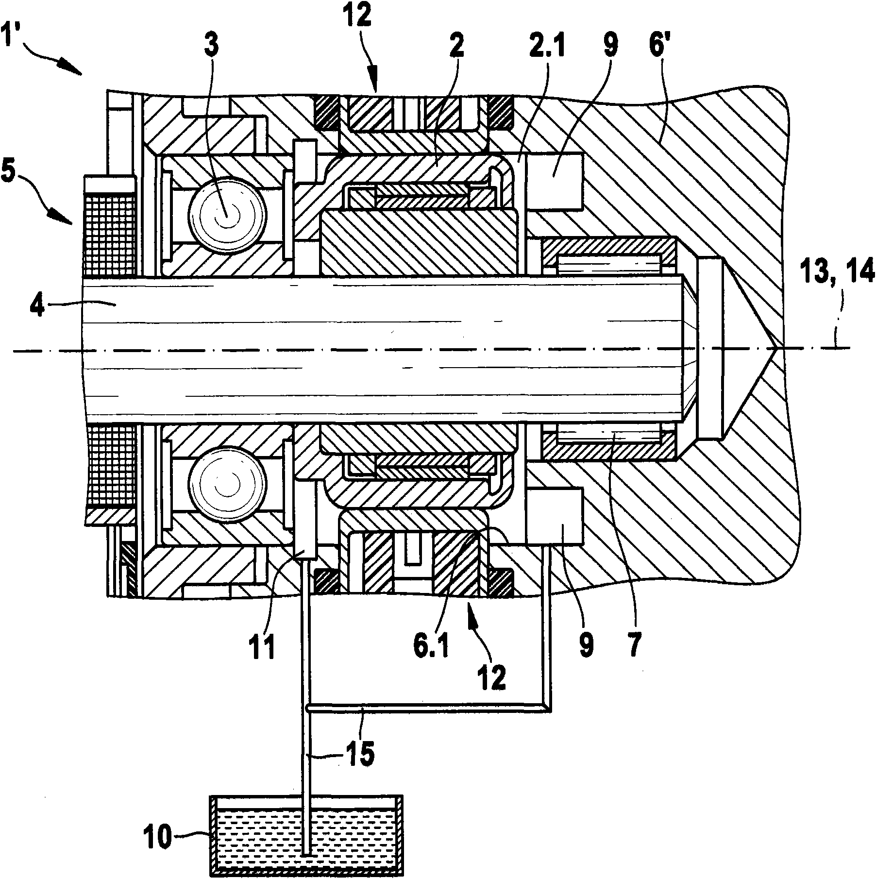
[0015] Corresponding parts are still provided with the same reference numerals in FIG. 2 . Components improved according to the invention are marked with primes.

[0016] The eccentric bearing 2 and the drive bearing 3 are arranged in the eccentric cavity 2.1 of the pump housing 6'. This eccentric cavity 2.1 is formed by means of a blind hole-shaped motor bore 6.1 on the pump housing 6'. The two pump elements 12 are located in corresponding pump bores of the pump housing 6'. The two pump bores extend radially on both sides of the eccentric cavity 2.1 and lie opposite each other in a straight line. The driv...


PUM


Abstract

The invention relates to a pump (1') comprising an eccentric bearing (2), a drive bearing (3), a drive shaft (4), an electric drive motor (5), and a pump housing (6'). The pump housing (6') is provided with an eccentric chamber (2.1), which is formed on the pump housing (6') by an engine bore (6.1) in the form of a blind hole. The pump (1') comprises compensating means (9, 11) that enlarge the eccentric chamber (2.1) of the eccentric bearing (2). According to the invention, said compensating means (9, 11) comprise at least one recess (11) arranged on the wall of the engine bore (6.1).

Description

technical field [0001] The invention relates to a pump according to the preamble of independent claim 1, in particular for a hydraulic system of an electronically controlled vehicle braking system. Background technique [0002] Such a pump is known, for example, from the earlier DE patent application number 102006016897.6. The pump has in particular a pump housing with an eccentric cavity in which an eccentric bearing is arranged. The eccentric cavity is formed by a blind hole-shaped motor bore. [0003] A drive motor that drives the eccentric bearing to make it rotate is connected to the pump casing with a flange. The rotating eccentric bearing drives the pump element placed in the pump casing to make reciprocating linear motion. The hydraulic medium is conveyed by the pump element. [0004] If the pump is designed, for example, as part of an ABS system (Antilock Braking System) and / or an ESP system (Electronic Stability System), it is possible during pump operation due...

Claims


Application Information

Patent Timeline
Patent Type & Authority Applications(China)
IPC IPC(8): F04B1/04B60T8/00
CPCB60T8/4031F04B1/0443
Inventor M·卡尔R·费尔梅特O·施毛茨R·施托茨
Owner ROBERT BOSCH GMBH
Why Eureka
Try Eureka