Solar cell having a dielectric rear face coating and method for producing same

A technology of solar cells and manufacturing methods, applied in the field of solar cells, can solve problems such as loss of efficiency and reduction of contact area, and achieve the effects of improving efficiency, preventing local short circuits, and improving efficiency

Active Publication Date: 2013-08-28
RCT SOLUTIONS
View PDF2 Cites 0 Cited by
  • Summary
  • Abstract
  • Description
  • Claims
  • Application Information

AI Technical Summary

Problems solved by technology

However, as practical results have shown, the width and height of the contacts must be reduced considerably in order to reliably prevent contact in the shadow area
Moreover, the significant reduction in contact area also results in a loss of efficiency due to increased resistance

Method used


Image

  • Solar cell having a dielectric rear face coating and method for producing same
  • Solar cell having a dielectric rear face coating and method for producing same
  • Solar cell having a dielectric rear face coating and method for producing same

Examples


Embodiment Construction

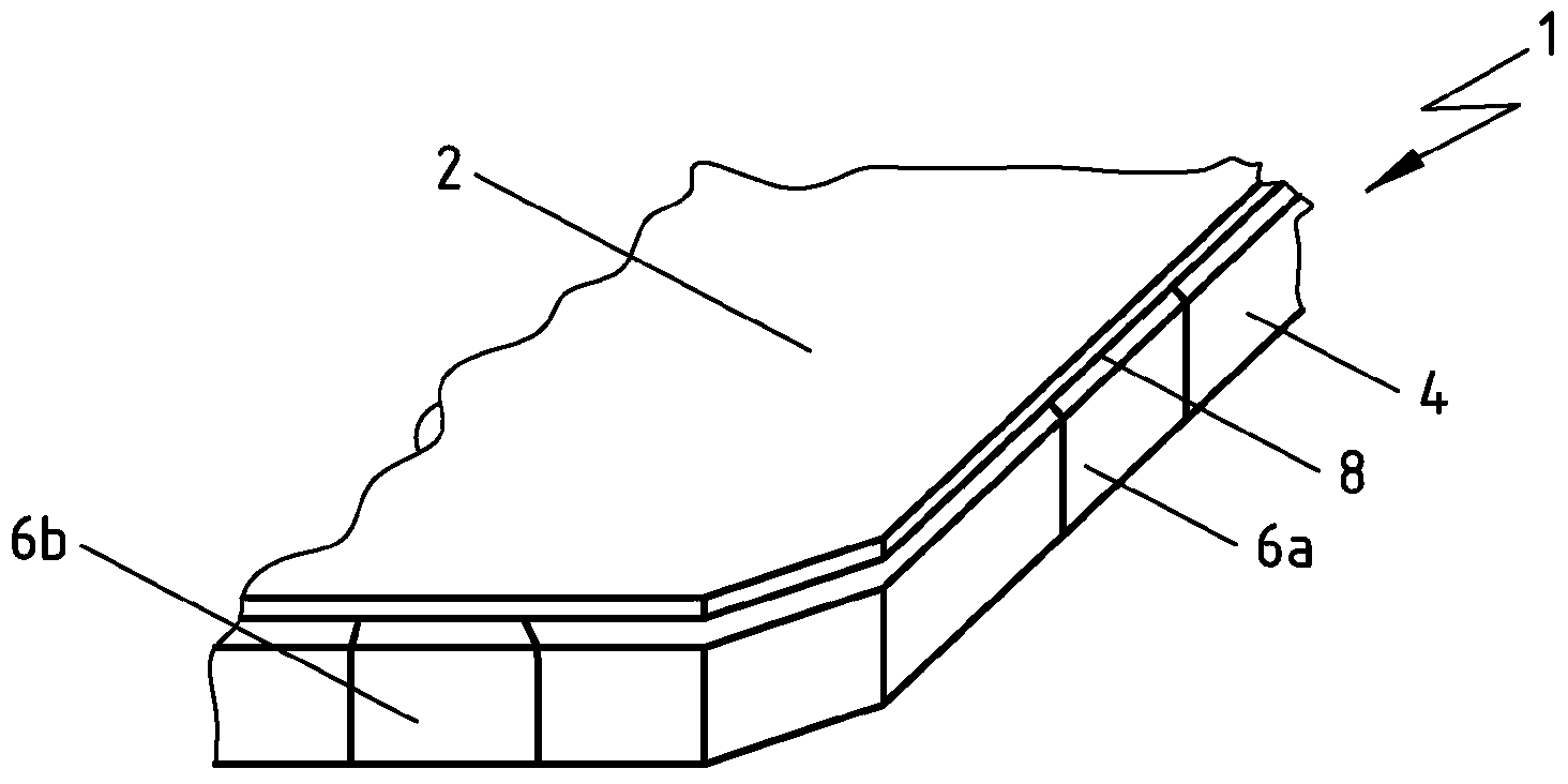
[0045] FIG. 1 shows a schematic perspective view of the back side of a solar cell 1 according to the prior art. On the rear side of the solar cell 1, a dielectric coating 4, for example an oxide-nitride coating, is arranged. It also partially covers the edges of the solar cell 11 . On the rear side of the solar cell 1 there is also arranged a planar contact 2 which partially covers the dielectric coating 4 . The planar contact 2 thus also covers the regions 6 a , 6 b that were covered by the retaining ring during the deposition of the dielectric coating 4 . These areas are shown in white in FIG. 1 . The masked areas 6a, 6b extend from the edge of the solar cell 1 to the back of the solar cell 1 and are not covered, or are only covered with a dielectric layer which is much thinner than the other areas of the solar cell whose back is covered by a dielectric coating 4 . Since the emitter dopant is diffused into the masked regions 6a, 6b of the solar cell 1 during the emitter ...


PUM


Abstract

The invention relates to a solar cell (11; 21; 31) comprising a dielectric coating (4) which is disposed on a rear face of the solar cell (11; 21; 31) and is covered at least partially by at least one flat contact (12; 22; 32), wherein a boundary line (14; 24; 34) of the at least one flat contact (12; 22; 32) has at least one recess (16a, 16b; 26a, 26b, 26c). The invention also relates to a method for producing same.

Description

technical field [0001] The invention relates to a solar cell and a method for producing a solar cell. Background technique [0002] In solar cells produced according to the prior art, a dielectric coating is often provided on the back side of the solar cell, ie the side facing away from the incident light in operation, as an optical mirror for the long-wave component of light. State-of-the-art production methods apply a dielectric coating even before the diffusion of the emitter on the solar cell substrate used to make the solar cell, and this dielectric coating is then used to prevent the diffusion of emitter dopants into the solar cell Diffusion barrier layer on the backside of the substrate. Additionally, the dielectric coating can be applied prior to texturing etch of the front side (ie the side of the solar cell substrate facing incident light in operation) and be used as an etch stop layer to prevent etching of the backside of the solar cell substrate. Such an advant...

Claims


Application Information

Patent Timeline
Patent Type & Authority Applications(China)
IPC IPC(8): H01L31/0224H01L31/18
CPCH01L31/022425H01L31/18H01L31/1804Y02E10/547H01L31/056Y02E10/52Y02P70/50
Inventor 安德里亚斯·特佩阿道夫·闵塞尔简·薛昂马赛厄斯·海恩彼得·温特尔
Owner RCT SOLUTIONS
Why Eureka
Try Eureka