Arc-extinguishing piece arrangement

A technology of arc extinguishing sheet and switch, which is applied in the direction of electrical components, electric switches, circuits, etc., to achieve good burning resistance and improve the effect of arc extinguishing

Inactive Publication Date: 2012-01-11
ABB (SCHWEIZ) AG
View PDF5 Cites 0 Cited by
  • Summary
  • Abstract
  • Description
  • Claims
  • Application Information

AI Technical Summary

Problems solved by technology

[0008] However, increasing the number of arc chute is limited by the structural space available in the plant and by the technical specification, which stipulates the minimum total air gap as the sum of the air gaps between the individual arc chute and the minimum leakage path (Mindest -Kreichweg) as a leakage path between adjacent sheets

Method used


Image

  • Arc-extinguishing piece arrangement
  • Arc-extinguishing piece arrangement
  • Arc-extinguishing piece arrangement

Examples


Embodiment Construction

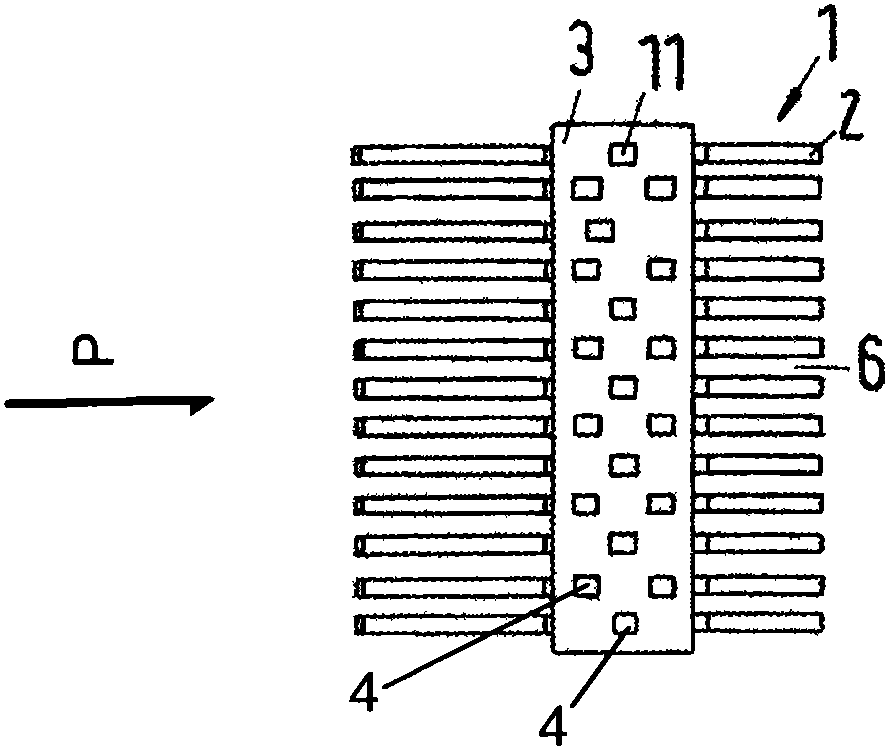
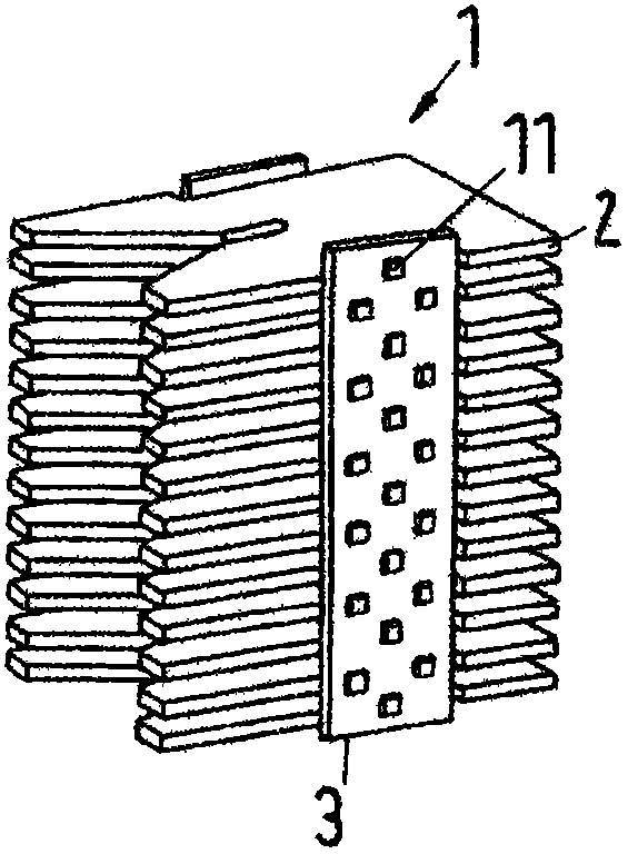
[0040] Figure 1a and Figure 1bA side view and a perspective view of an interrupter arrangement 1 known from the prior art are shown in each case. The individual quenching plates 2 all have the same thickness and the same distance 6 from one another and are connected in the central region by a support means 3 in the form of a support strip 3 . The support strip 3 has a support component 4 in the form of a hole 4 into which a nub-shaped projection 11 engages on the narrow side of the arc extinguisher 2 . As a result, the interrupters 2 are supported by support strips and their mutual spacing is determined. The openings 4 are arranged with a fixed grid size (Rastermass), which is chosen to correspond to the minimum permissible distance between two adjacent quenching plates. Next, alternating one hole and one pair of holes from top to bottom, the arc chute with a single or a pair of existing nubs is applied accordingly. in accordance with Figure 1a and Figure 1b In the emb...


PUM


Abstract

The invention describes an arc-extinguishing piece arrangement (1) for an electric installation switch device, in particular for a line protection switch, a motor protection switch or an earth leakage protection switch. The arc-extinguishing piece arrangement (1) has arc-extinguishing pieces (2) which are stacked in parallel between a first guide plate and a second guide plate to a predeterminable stack height. The arc-extinguishing pieces (2) are supported at intervals by at least one supporting device (3) made of insulating materials. For adaption to the short-circuit current limit caused by the arc-extinguishing piece arrangement (1), under the circumstance of maintaining the predetermined stack height, the total amount of the arc-extinguishing pieces is the sum of the first amount of the first arc-extinguishing pieces with a first thickness and the second amount of the second arc-extinguishing pieces with a second thickness, wherein the second thickness is less than the first thickness.

Description

technical field [0001] The invention relates to an arc chute arrangement according to the preamble of claim 1 for an electrically installed switchgear, in particular for a line protective switch or a motor protective switch, which has a stacked form with a predeterminable stack height Between the first guide plate and the second guide plate are arranged parallel to one another the quenching plates, wherein the quenching plates are supported at a distance from one another by means of at least one support means made of insulating material. [0002] Furthermore, the invention relates to an installation switchgear, in particular to a circuit breaker or earth-leakage circuit breaker, which has an interrupter arrangement for an electrical installation switchgear, in particular for a circuit breaker or a motor protection switch, The arc chute arrangement has arc chute arranged parallel to one another between a first guide plate and a second guide plate in a stack of a predeterminable...

Claims


Application Information

Patent Timeline
Patent Type & Authority Applications(China)
IPC IPC(8): H01H9/34
Inventor K・齐默尔
Owner ABB (SCHWEIZ) AG
Why Eureka
Try Eureka