Attenuation Devices for Power Electronics Applications

A technology of attenuation device and power electronics, applied in circuit devices, output power conversion devices, measurement devices, etc., can solve the problems of component wear and failure, etc.

Active Publication Date: 2022-02-08
ZF FRIEDRICHSHAFEN AG
View PDF19 Cites 0 Cited by
  • Summary
  • Abstract
  • Description
  • Claims
  • Application Information

AI Technical Summary

Problems solved by technology

However, due to the small space between the individual components, this design causes wear between the individual components under vibration loads and can lead to consequences as severe as the failure of the individual components, including the LV current sensor

Method used


Image

  • Attenuation Devices for Power Electronics Applications

Examples


Embodiment Construction

[0020] The proposed attenuation device for power electronics applications is advantageously used in shaft drives. It is advantageously used in vehicles that are at least partially electrically driven or fully electrically driven.

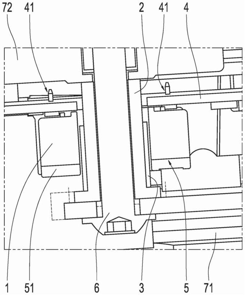
[0021] The object of the invention is to reduce or even avoid vibration loads between the current sensors, more precisely between the current sensor housing 1 surrounding the current sensor or in which the current sensor is arranged, and the electrical contact pin 2 . Another object is to achieve a low load on the connection point 41 between the current sensor and the circuit board 4 , which connection point is usually designed as a soldering point, due to vibration excitation. The probability of component failure is thus also reduced.

[0022] In an application in the field of power electronics for shaft drives described in the form of an exemplary embodiment below, the current sensor conducts a low voltage, and is therefore an LV current sensor, ...


PUM


Abstract

An attenuation device for power electronics applications is provided, the attenuation device having: a circuit board (4); and a current sensor electrically connected to the circuit board (4) and held in a current sensor housing (1); and a current needle (2), the current needle (2) extending through the circuit board (4) and surrounded by the current sensor housing (1), the attenuation element (3) is arranged in between the current sensor housing (1) and the current needle (2).

Description

technical field [0001] The invention relates to an attenuation device for power electronics applications. Background technique [0002] Use the following abbreviations: [0003] AC stands for alternating current. [0004] DC stands for direct current. [0005] LV stands for low voltage. [0006] HV stands for High Voltage. [0007] Various designs are known for power electronics applications of shaft drives. For example, there are LV-AC current sensors with a one-piece housing. However, due to the small diameter for the HV electrical contact pins, that is to say due to the reduced cross-section, less current can be transferred, or more self-heating is generated. [0008] Currently, two-piece housings are used for LV current sensors, where the cross-section in this region is significantly reduced in order to maintain the air gap and creepage path between the LV current sensor and the HV electrical contact pins. In order to create the required air gap and creepage path ...

Claims


Application Information

Patent Timeline
Patent Type & Authority Patents(China)
IPC IPC(8): H05K7/14B60L15/00H02M7/00G01R19/00G01R15/14H02M1/00
CPCB60L15/007H05K7/1432B60L2270/145Y02T10/64G01R19/0046H05K1/0213H05K1/181H05K2201/0753H05K2201/10151
Inventor 伊沃内·特伦茨
Owner ZF FRIEDRICHSHAFEN AG
Why Eureka
Try Eureka