heat exchanger unit

A technology of heat exchangers and heating devices, which is applied in the direction of electrical devices, control devices, battery/fuel cell control devices, etc., and can solve the problem of being unable to heat the area to be heated, such as waste heat

Inactive Publication Date: 2014-10-22
WEBASTO AG
View PDF6 Cites 0 Cited by
  • Summary
  • Abstract
  • Description
  • Claims
  • Application Information

AI Technical Summary

Problems solved by technology

[0003] In hybrid vehicles with an electric drive motor and an internal combustion engine drive engine and in electric vehicles with only one electric drive motor, the problem arises to a greater extent that it is not possible to drive the device from the vehicle in all operating states. Obtain sufficient waste heat for heating the area to be heated

Method used


Image

  • heat exchanger unit

Examples


Embodiment Construction

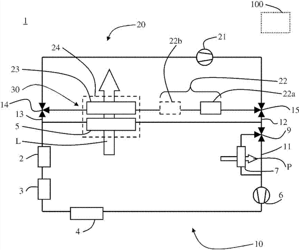
[0026] Refer below figure 1 An embodiment is described. figure 1 A vehicle (vehicle) heating circuit 1 is shown according to one embodiment. In the embodiment shown, the vehicle heating circuit 1 is implemented in an electric vehicle driven by an electric machine 2 . Power electronics 3 are provided forming the electronic components of the powertrain. In addition, an accumulator 4 is provided for supplying the power electronics 3 and the electric machine 2 with electrical energy. The accumulator 4 , the power electronics 3 and the electric machine 2 form the vehicle electrical component to be cooled. During operation (at least in some operating states of the vehicle), heat must be dissipated from these components to be cooled to ensure that operation is maintained and / or to prevent damage to the components.

[0027] components to be cooled, i.e., in figure 1 The accumulator 4 , the power electronics 3 and the electric machine 2 in the case shown in are connected to a firs...


PUM


Abstract

A heat exchanger arrangement is made available for heating an area of a vehicle which is to be heated, having: a first heat exchanger element for transmitting waste heat from at least one vehicle electrical component to be cooled to air, and a second heat exchanger element for transmitting heat from at least one vehicle heating device to air. The first heat exchanger element and the second heat exchanger element are arranged in such a way that air (L) to be heated is successively applied to them.

Description

technical field [0001] The invention relates to a heat exchanger arrangement for heating a region to be heated of a vehicle. Background technique [0002] It is known to heat a region to be heated of a vehicle, such as the interior of a motor vehicle, by means of a heat exchanger arrangement, to which the air to be heated is applied (i.e. the air to be heated is caused to flow around said heat exchanger arrangement or The air to be heated flows through said heat exchanger means) and supplies said air to the area to be heated. In conventional road vehicles with an internal combustion engine, the waste heat of the internal combustion engine is usually used for heating, since the hot engine coolant passes through a heat exchanger arrangement in which heat is transferred to the air to be heated ) is transmitted. In modern high-efficiency internal combustion engines, the released heat is often no longer sufficient to adequately heat the passenger compartment, with the result th...

Claims


Application Information

Patent Timeline
Patent Type & Authority Patents(China)
IPC IPC(8): B60H1/00B60H1/03F01P3/00
CPCB60H1/034B60H2001/00307B60H1/00385B60L3/003B60L1/003B60L11/1874B60L11/1805B60L1/02B60L2240/36B60L11/1875F01P2060/08B60L3/0061B60L2240/34B60L50/52B60L58/26B60L58/27Y02T10/70
Inventor M·伦纳T·克佩
Owner WEBASTO AG
Why Eureka
Try Eureka