Method of making a colour filter array
A color filter array, atmospheric technology, applied in instruments, filters, photoengraving process of pattern surface, etc., can solve complex problems and achieve the effect of less assembly labor
- Summary
- Abstract
- Description
- Claims
- Application Information
AI Technical Summary
Problems solved by technology
Method used
Image
Examples
example 1
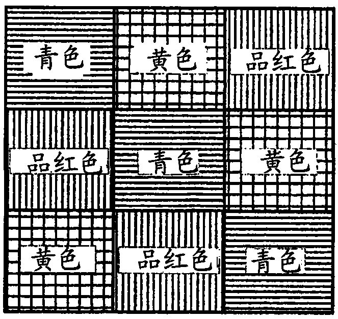
[0047] A simple color filter array was fabricated by a combination of ALD and inkjet printed P604A by printing fluoropolymer squares to act as resist for the ALD layer. A 62 x 62 x 1 mm glass slide was first coated with a thin layer of aluminum by vacuum evaporation, followed by an approximately 200 nm thick layer of titanium oxide deposited by ALD.
[0048] A mixture of 25% w / w Fluoropel (fluorinated polymer) P604A + 75% perfluorodecalin was prepared and loaded into a Dimatix inkjet printer as described in the specification. A row of three 5 mm squares of P604A was printed with a full ink Dimatix printer as shown in Figure 5a. As shown in Figure 5b, next, the sample was coated with an approximately 50 nm thick layer of titanium oxide before printing an additional three 5 mm squares of fluoropolymer to complete the 3x3 matrix. After laying down the last layer of titanium oxide about 50nm thick, the fluoropolymer was removed using HFE 7500 solvent and gentle rubbing with nitri...
example 2
[0050] Repeat Example 1 using PVP as the mask material.
[0051] Fabricate a simple color filter array. A 62 x 62 x 1 mm glass slide was first coated with a thin layer of aluminum by vacuum evaporation, followed by an approximately 200 nm thick layer of titanium oxide deposited by ALD.
[0052] A PVP inkjet ink consisting of 10% K30, 10% ethylene glycol and 1% Triton (trinitrotoluene) X-100 was made. The latter two ingredients are added to help with jetting. A row of three 5 mm squares of PVP ink was printed using a Dimatix printer filled with ink as shown in Figure 5a. As shown in Figure 5b, next, the sample was coated with an approximately 50 nm thick titanium oxide layer before printing the other three 5 mm squares of PVP ink to complete the 3x3 matrix. After the last ~50 nm thick layer of titanium oxide, the PVP ink was removed by dipping in warm deionized water and rubbing gently with nitrile gloved hands.
[0053] A thin layer of aluminum is applied on top of this by...
example 3
[0055] Fabrication of complex color filter arrays.
[0056] A 62 x 62 x 1 mm glass slide was first coated with a "Bragg reflector" of 5 alternating layers of alumina and titania, each about 100 nm thick, starting with low index alumina and Finish. On top of this is deposited an approximately 200 nm thick layer of titanium oxide.
[0057] A mixture of 25% w / w Fluoropel (fluorinated polymer) P604A + 75% perfluorodecalin was prepared and loaded into a Dimatix inkjet printer as described in this specification. A row of three 5mm squares of P604A was printed using a Dimatix printer filled with ink as shown in Figure 5a. As shown in Figure 5b, next, the sample was coated with an approximately 50 nm thick layer of titanium oxide before printing an additional three 5 mm squares of fluoropolymer to complete the 3x3 matrix. After the last layer of titanium oxide about 50nm thick, the fluoropolymer was removed by using HFE 7500 solvent and rubbing gently with nitrile gloved hands.
...
PUM
 Abstract
Description
Claims
Application Information
 - R&D Engineer
- R&D Manager
- IP Professional
- Industry Leading Data Capabilities
- Powerful AI technology
- Patent DNA Extraction
Browse by: Latest US Patents, China's latest patents, Technical Efficacy Thesaurus, Application Domain, Technology Topic, Popular Technical Reports.
© 2024 PatSnap. All rights reserved.Legal|Privacy policy|Modern Slavery Act Transparency Statement|Sitemap|About US| Contact US: help@patsnap.com


