Conveying device

A technology for conveying devices and transmission belts, which is applied in the direction of conveyors, conveyor objects, transportation and packaging, etc., which can solve problems such as excessive time spent, wear of conveying rollers, damage to glass substrates, etc., to reduce maintenance costs and time, and increase conveying speed , Reduce the effect of rolling friction

Inactive Publication Date: 2010-08-25
AU OPTRONICS CORP
View PDF6 Cites 22 Cited by
  • Summary
  • Abstract
  • Description
  • Claims
  • Application Information

AI Technical Summary

Problems solved by technology

If the motors of each conveying device 1 cannot be adjusted to drive synchronously, the bottom of the glass substrate cassette and the conveying roller 10 will also be worn away, resulting in a large amount of dust
Furthermore, since the conveying device 1 of each section needs to be driven at the same time, and the mechanical structure of the conveying device 1 is complex, a relatively high-power motor needs to be selected, which will cause excessive power consumption and increase the cost
[0004] (2) It is necessary to regularly check whether the chain 14 is too loose. The chain 14 and the gear 16 need to be lubricated. Not only is adjustment and maintenance difficult, the structure is complicated, and the maintenance cost is high
In addition, when the chain 14 drives the gear 16 to rotate, there will also be oil and gas problems, which will contaminate the glass substrate
[0005] (3) It is not easy to adjust the parallelism of the conveying rollers 10. In addition, under long-term use, the parallelism of the conveying rollers 10 will also run away.
It takes extra time and labor costs to maintain and overhaul the parallelism of the conveying rollers 10
[0006] (4) The existing conveying device 1 mainly uses guide rollers 12 on both sides to guide the glass substrate cassettes. If the glass substrate cassettes are constantly in contact with the guide rollers 12 during the conveying process , will cause the guide roller 12 to wear, and then generate dust
In addition, if several guide rollers 12 are particularly worn, the glass substrate cassette will vibrate during the conveying process, causing the glass substrate in the glass substrate cassette to shift, resulting in damage to the glass substrate
[0007] (5) Use the pneumatic cylinder as the brake 20, not only the cost of the pneumatic cylinder is relatively high, but also the cost of air supply needs to be additionally borne, thus increasing the installation cost of the conveying device 1
If the conveying device 1 is capable of two-way conveying, then both sides of the conveying device 1 must be equipped with brakes 20, and the cost will be further increased.

Method used


Image

  • Conveying device
  • Conveying device
  • Conveying device

Examples


Embodiment Construction

[0042] In order to have a clearer understanding of the technical features, purposes and effects of the present invention, the specific implementation manners of the present invention will now be described with reference to the accompanying drawings.

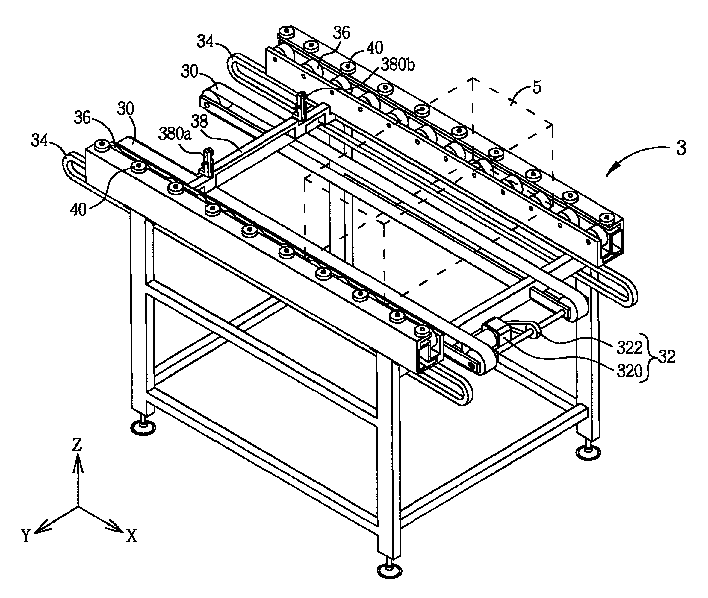
[0043] Please refer to FIG. 3 and FIG. 4 , FIG. 3 is a perspective view of the delivery device 3 according to an embodiment of the present invention, and FIG. 4 is a top view of the delivery device 3 in FIG. 3 . As shown in FIGS. 3 and 4 , the conveying device 3 includes two transmission belts 30 , a driving mechanism 32 , two guide rails 34 , a plurality of first rollers 36 , a first pushing platform 38 and a plurality of second rollers 40 . The driving mechanism 32 is connected to the transmission belt 30 for driving the transmission belt 30 . In this embodiment, the driving mechanism 32 may include a motor 320 and a connecting rod 322 , wherein the connecting rod 322 is connected to one end of the transmission belt 30 , and th...


PUM


Abstract

The invention discloses a conveying device for conveying an object. The conveying device comprises a transmission belt, a drive mechanism, a guide railway, a plurality of first rollers and a first push platform, wherein the drive mechanism is connected with the transmission belt for driving the transmission belt; the guide railway is arranged at one side of the transmission belt; the plurality of first rollers are arranged into a row, and are arranged above the guide railway in free rotation, and objects are placed on the plurality of first rollers; the first push platform is connected with the transmission belt, and is spanned on the guide railway; and when the drive mechanism drives the transmission belt, the first push platform is driven by the transmission belt to push the objects, so that the objects can move on the plurality of first rollers.

Description

technical field [0001] The invention relates to a conveying device, in particular to a conveying device which can be used to convey glass substrate cassettes. Background technique [0002] Please refer to FIG. 1 and FIG. 2 , FIG. 1 is a top view of a conventional conveying device 1 , and FIG. 2 is a side view of the conveying device 1 in FIG. 1 . As shown in FIGS. 1 and 2 , the conveying device 1 includes a plurality of conveying rollers 10 , a plurality of guide rollers 12 , a chain 14 , a plurality of gears 16 , a motor 18 and a stopper 20 . In practical applications, objects such as glass substrate cassettes can be placed on the conveying rollers 10 for conveying. The conveying device 1 drives the chain 14 through the motor 18 , and then drives the gear 16 to rotate the conveying roller 10 . At this time, the glass substrate cassettes placed on the transport rollers 10 will be transported forward. The guide rollers 12 arranged on both sides of the conveying device 1 ca...

Claims


Application Information

Patent Timeline
Patent Type & Authority Applications(China)
IPC IPC(8): B65G49/06B65G19/02B65G19/18B65G19/24
Inventor 李志伟谢承勋
Owner AU OPTRONICS CORP
Why Eureka
Try Eureka