
Detection device for load of rolling bearing and detection method thereof

A rolling bearing and testing device technology, applied in the direction of mechanical bearing testing, etc., can solve the problem of no rolling bearing dynamic load testing, etc., to save testing time, improve testing efficiency, and facilitate installation and disassembly.

Inactive Publication Date: 2010-08-25
ZHEJIANG SANY EQUIP
View PDF7 Cites 5 Cited by
  • Summary
  • Abstract
  • Description
  • Claims
  • Application Information

AI Technical Summary

Problems solved by technology

At present, there is no equipment on the market for dynamic load testing of heavy-duty rolling bearings

Method used


Image

  • Detection device for load of rolling bearing and detection method thereof
  • Detection device for load of rolling bearing and detection method thereof

Examples


Embodiment 1

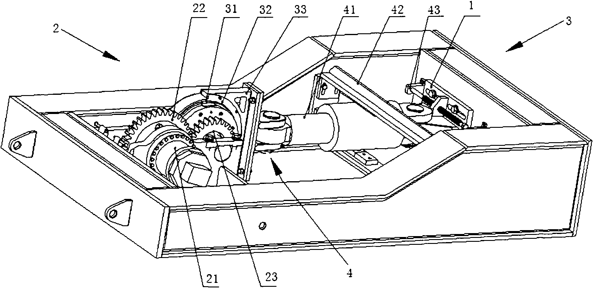
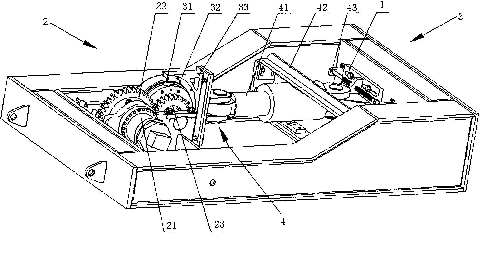
[0034] Embodiment 1: Please refer to Fig. 1, a rolling bearing load detection device, including a base 1, a power transmission mechanism 2 arranged at the front end of the base 1, a connection connected to the power transmission mechanism 2 and arranged behind the power transmission mechanism 2 The mechanism 3 and the loading mechanism 4; The power transmission mechanism 2 includes a hydraulic motor 21, a large gear 22 and a small gear 23; the rotating shaft of the hydraulic motor 21 is connected with the large gear 22 to drive the large gear 22 to rotate; the large gear 22 and the small gear 23 are meshed and connected, and the large gear 22 drives the small gear 23 turns. The connection mechanism 3 includes a bearing sleeve 31 , a copper lining 32 arranged above the bearing sleeve 31 and moving relative to the bearing sleeve 31 , and a pressing plate 33 connected with the copper lining 23 . The pinion 23 is connected with the bearing sleeve 31 by a key, and the pinion 23 dr...

Embodiment 2

[0046] Embodiment 2: As shown in Figure 1, the hydraulic motor 21 installed on the base 1 is driven to rotate by the hydraulic pump station, driving the large gear 22, and then pushing the pinion 23 to rotate; the pinion 23 is rigidly connected with the bearing sleeve 31, thereby driving Bearing sleeve 31 rotates. The bearing sleeve 31 will rotate synchronously with the outer ring of the bearing, and its speed is equal to that of the pinion 23 .

[0047] While the bearing is rotating, the oil cylinder 41 also applies a radial load to the bearing. The load applied by the oil cylinder 41 acts on the copper lining 32 that rotates relative to the outer ring of the bearing sleeve 31 through the pressure block 33. The overall structure is similar to a sliding bearing, and the static load of the oil cylinder 41 is transmitted and evenly distributed and acts on the outer ring of the bearing. On the ring, instead of point contact and line contact, it can not only apply a unidirectiona...


PUM


Abstract

The invention relates to a detection device for a load of a rolling bearing, which comprises a base, a power transmission mechanism arranged in the most front end of the base, a connection mechanism connected with the power transmission mechanism and arranged at the back of the power transmission mechanism and a loading mechanism, wherein the loading mechanism is arranged in the rearmost end of the base and connected with the connection mechanism. In the invention, the actual working conditions of different types of bearings can be simulated truly, the bearing ability of the bearing, especially the dynamic load ability can be checked, , the normal bearing load of the rolling bearing for the components and the products can be ensured, the rolling bearing having normal appearance quality but the loading ability out of the design requirement caused by the internal defects, such as process and material can be discovered, and the failure rate of the rolling bearing is reduced.

Description

technical field [0001] The invention relates to a bearing detection device, in particular to a rolling bearing loading detection device and a detection method thereof. Background technique [0002] Rolling bearings are very important components of hoisting machinery, and their quality directly affects the quality, reliability and operating safety of the complete machine. Rolling bearings used in crawler cranes are subject to heavy loads, and their quality requirements are very high. At present, there is no equipment on the market for dynamic load testing of heavy-duty rolling bearings. [0003] The invention discloses a rolling bearing loading detection device and a detection method for such crawler crane pulley rolling bearings, and establishes an effective pulley rolling bearing loading detection test means. Contents of the invention [0004] The object of the present invention is to provide a rolling bearing loading detection device and its detection method, which is ...

Claims


Application Information

Patent Timeline
IPC IPC(8): G01M13/04
Inventor 江小冬李洪江吴森鹏
Owner ZHEJIANG SANY EQUIP
Learn More