WiFi (Wireless Fidelity) optical fiber radio central control system
A central control system, optical fiber radio technology, applied in electromagnetic wave transmission system, optical fiber transmission, wireless communication, etc., can solve problems such as connection interruption, achieve simple structure, reduce equipment cost, and easy expansion
Active Publication Date: 2010-08-25
广州飞瑞敖电子科技股份有限公司
View PDF4 Cites 16 Cited by
- Summary
- Abstract
- Description
- Claims
- Application Information
AI Technical Summary
Problems solved by technology
When a WiFi device roams from the coverage area of one access point to the coverage area of another access point, it needs to re-access, authenticate, which will cause the connection to be interrupted
Method used
View moreImage
Smart ImageViewing Examples
Examples
Embodiment Construction
Login to View More PUM
 Abstract
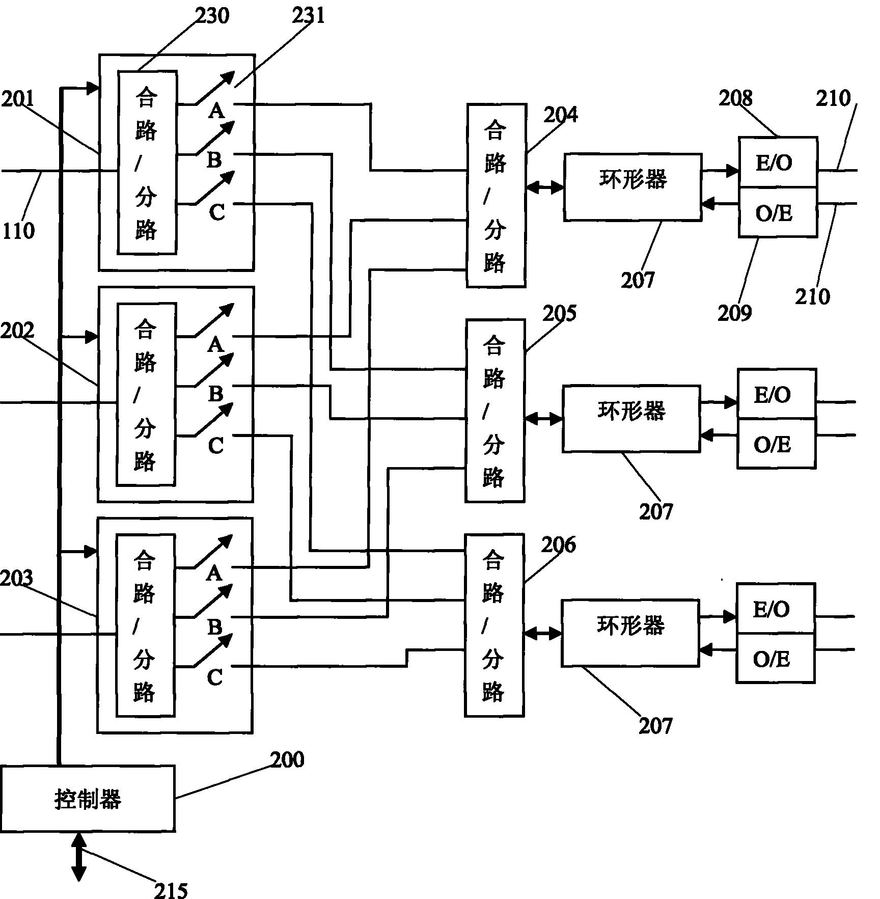
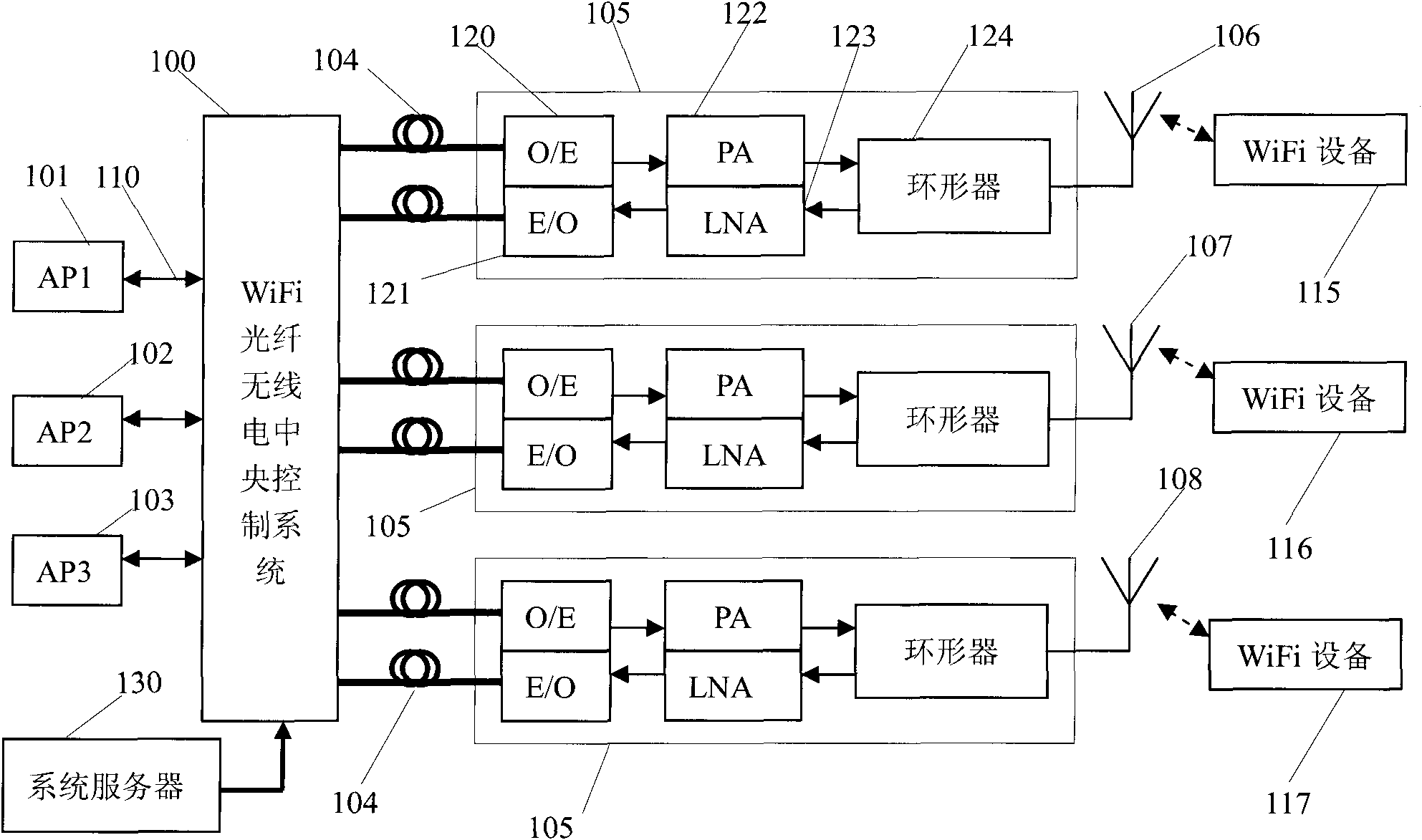
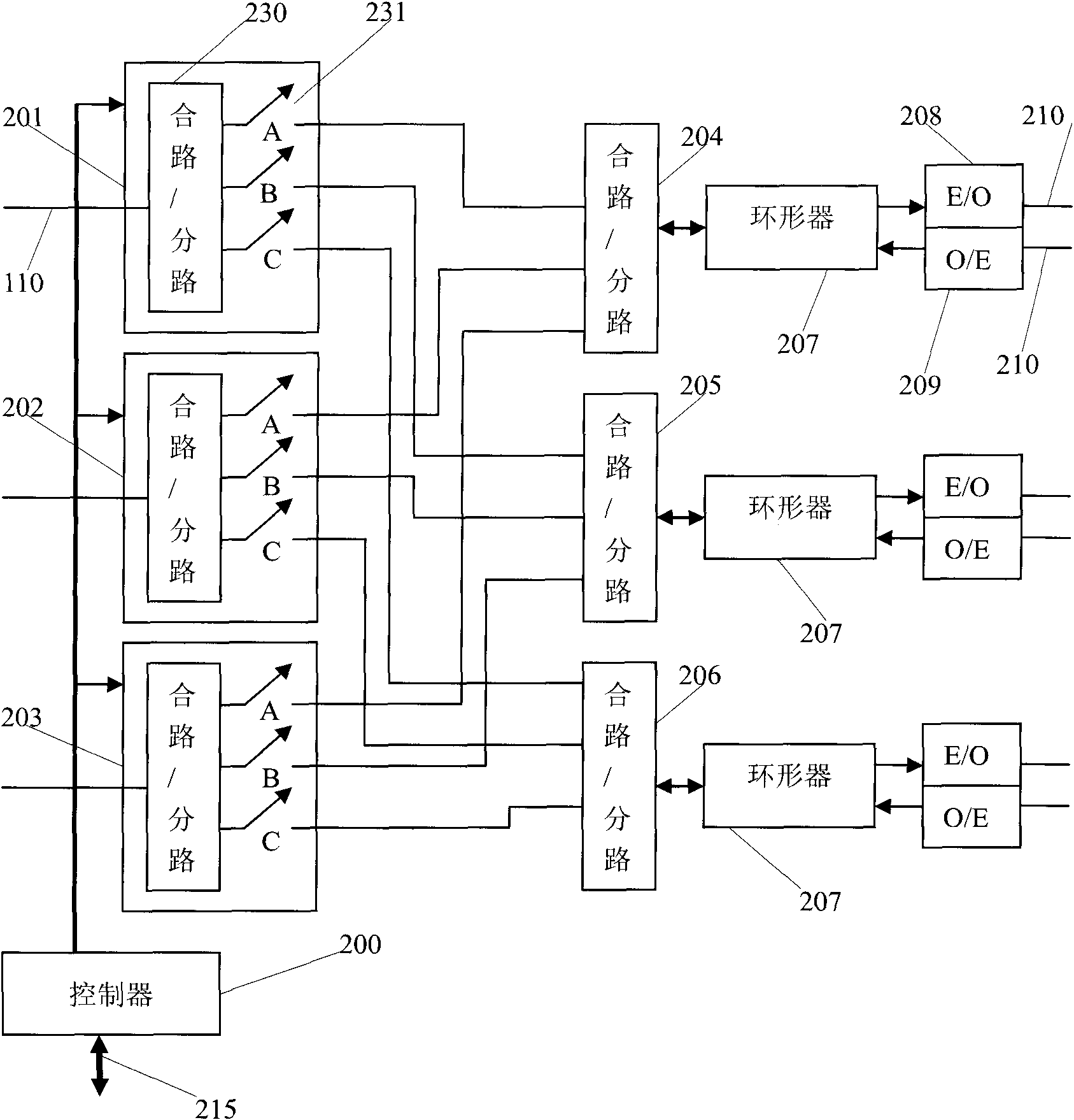
The invention discloses a WiFi (Wireless Fidelity) optical fiber radio central control system which comprises a controller, n radio-frequency signal distribution units and n radio-frequency branches, wherein each radio-frequency branch comprises a second combiner / shunt, a circulator, an electro-optical conversion module and an optical-electro conversion module; each radio-frequency signal distribution unit comprises a first combiner / shunt, n radio-frequency switches and a radio-frequency interface connected with the first combiner / shunt, and one ends of the n radio-frequency switches are connected to the first combiner / shunt, while the other ends are respectively connected to the n second combiners / shunts; and all the radio-frequency switches are independently controlled by a controller. The invention combines a radio-frequency switching technology, an optical fiber subcarrier multiplexing (SCM) technology and an optical fiber radio technology, and realizes the distribution, the switching and the optical fiber distribution of WiFi radio-frequency signals.
Description
WiFi fiber optic radio central control system technical field The present invention relates to a WiFi fiber optic radio central control system, in particular to a controller, a radio frequency signal distribution unit, a combiner / splitter, a circulator, an electrical / optical conversion module (E / O), an optical / electrical conversion module (O / E ). The WiFi radio frequency signal distribution, routing and optical fiber distribution are realized through the WiFi fiber optic radio central control system, which is used for intelligent, large-scale and flexible distribution of WiFi signals. Background technique At present, WiFi wireless local area network is becoming more and more popular, and has become the first choice for establishing a wireless local area network. However, the signal coverage range of a common WiFi access point (AP) is: indoors, 50-100 meters; outdoors, 100-150 meters. In order to expand the coverage of WiFi signals, the main methods adopted are: increasi...
Claims
Login to View More Application Information
Patent Timeline
 Patent Type & Authority Applications(China)
IPC IPC(8): H04B10/12H04W84/12H04B10/25
Inventor 庞文凤孟学军梅仲豪
Owner 广州飞瑞敖电子科技股份有限公司
Features
- R&D
- Intellectual Property
- Life Sciences
- Materials
- Tech Scout
- Unparalleled Data Quality
- Higher Quality Content
- 60% Fewer Hallucinations
Learn More Browse by: Latest US Patents, China's latest patents, Technical Efficacy Thesaurus, Application Domain, Technology Topic, Popular Technical Reports.
© 2025 PatSnap. All rights reserved.Legal|Privacy policy|Modern Slavery Act Transparency Statement|Sitemap|About US| Contact US: help@patsnap.com


