Structure of exhaust gas separation device of internal combustion engine

A technology of exhaust gas and separation device, applied in the direction of internal combustion piston engine, valve device, combustion engine, etc., can solve problems such as excessive labor and cost, poor sliding of hydraulic cylinder, difficulty in removing flash cutting chips, etc.

Inactive Publication Date: 2010-09-01
MITSUI ENG & SHIPBUILD CO LTD
View PDF9 Cites 3 Cited by
  • Summary
  • Abstract
  • Description
  • Claims
  • Application Information

AI Technical Summary

Problems solved by technology

[0028] However, since the hydraulic passages 131 to 136 of the hydraulic cylinder block 117 are formed by machining (drilling), the machining is complicated, and it is difficult to remove burrs (curling) or cutting chips (chips) during drilling. , there is a problem that more labor and cost are required for subsequent processing
In addition, when cutting chips (chips) remain in the hydraulic passage even in a small amount, there is a problem that it may cause poor sliding of the hydraulic cylinder.

Method used


Image

  • Structure of exhaust gas separation device of internal combustion engine
  • Structure of exhaust gas separation device of internal combustion engine
  • Structure of exhaust gas separation device of internal combustion engine

Examples


Embodiment Construction

[0096] refer to Figure 1 to Figure 6 Embodiments of the invention for implementing the structure of an exhaust gas separation device for an internal combustion engine of the present invention will be described in detail.

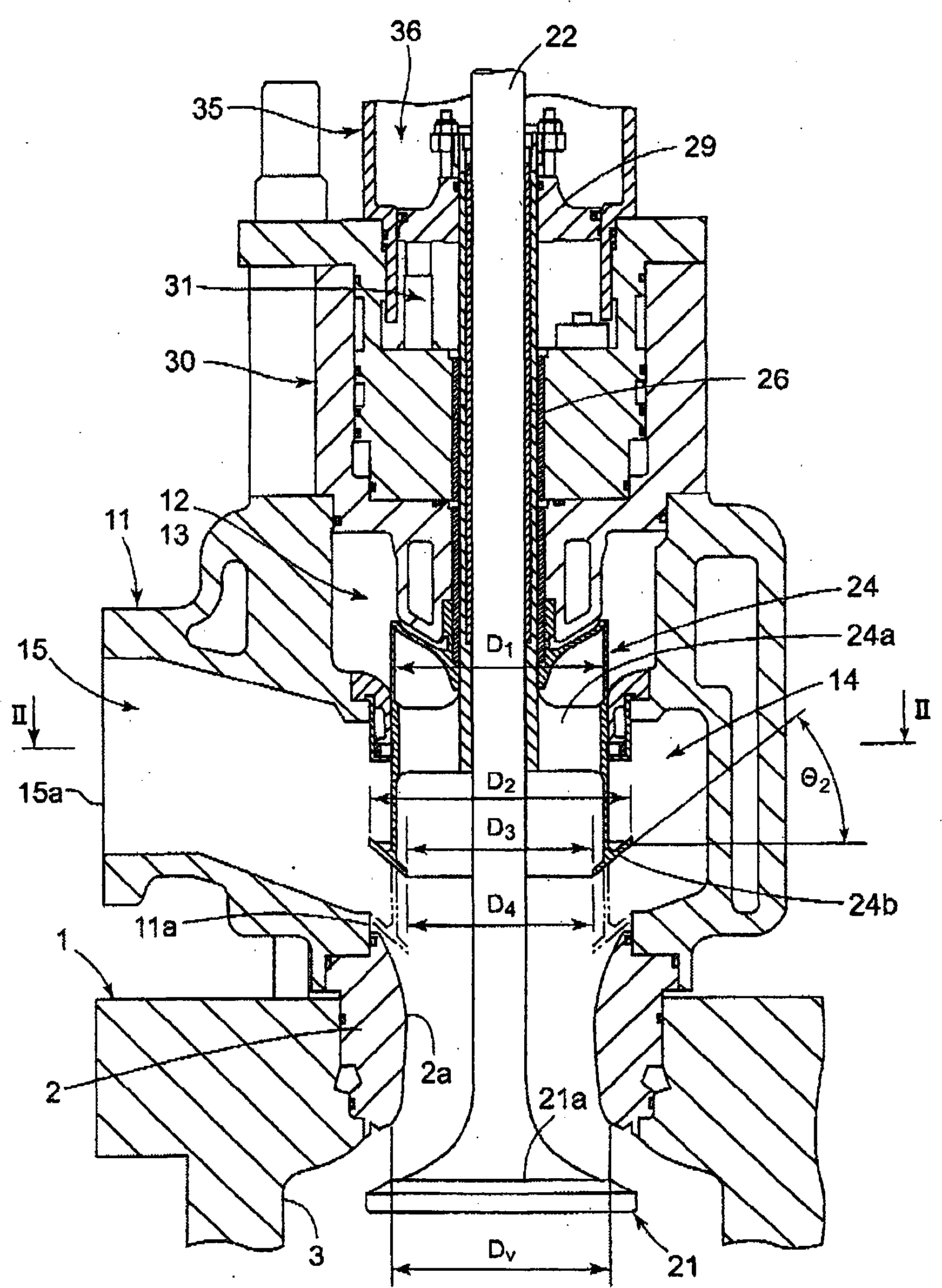
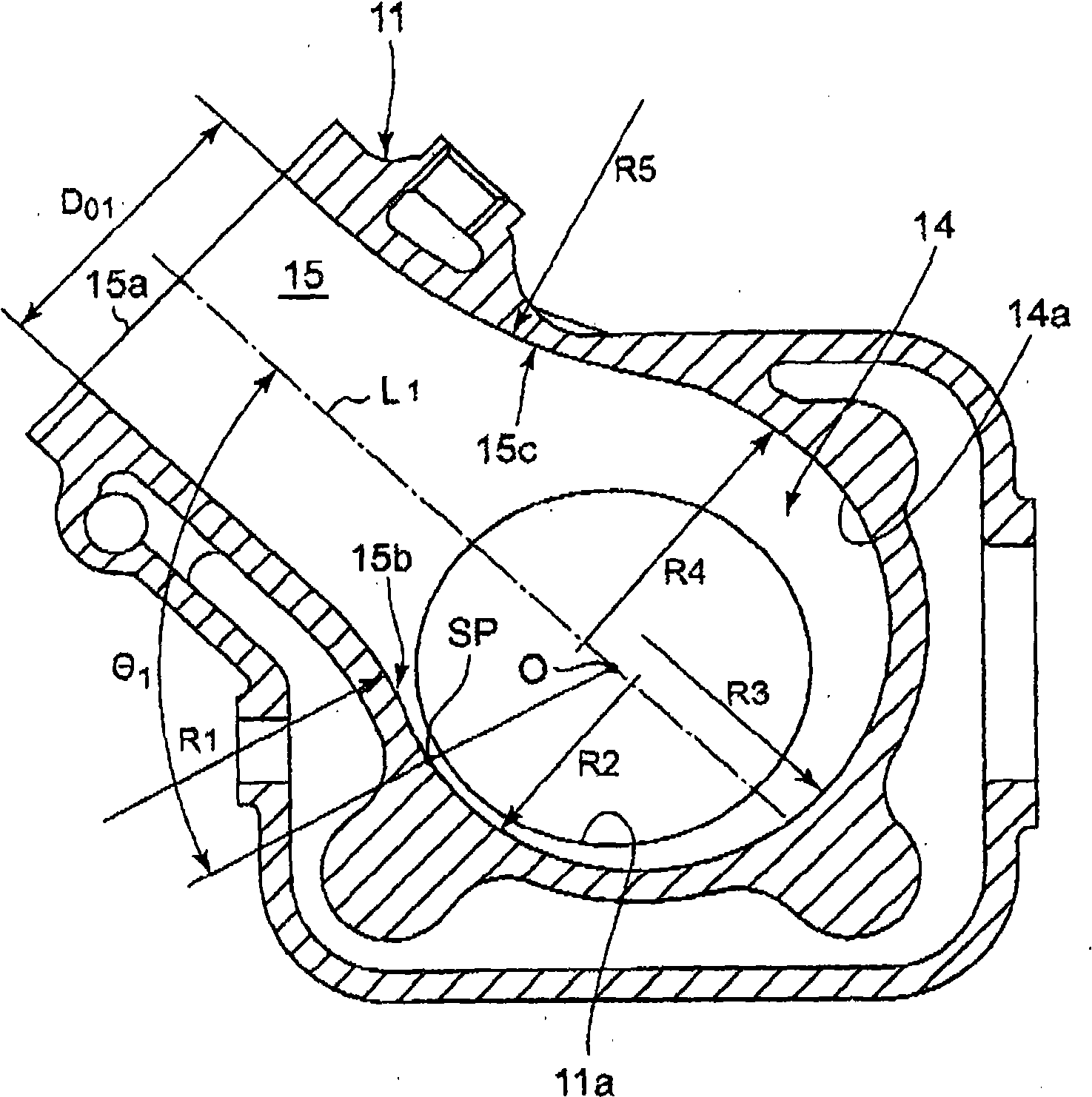
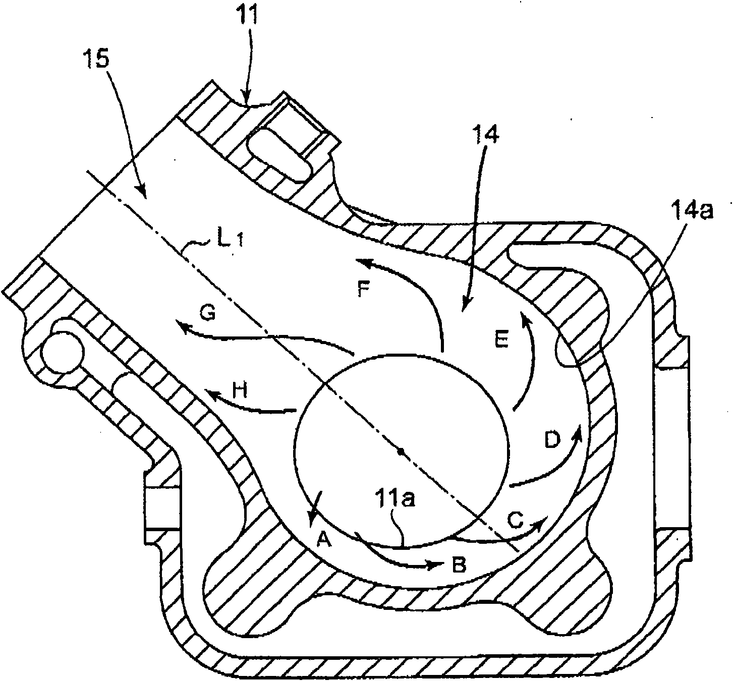
[0097] figure 1 It is a sectional view of main parts centering on the exhaust valve box 11 of a diesel engine to which the structure of the exhaust gas separation device for an internal combustion engine according to the present invention is applied. Such as figure 1 As shown, the exhaust valve box 11 is installed on the valve seat 2 of the cylinder body 1, and includes a main valve 21, a high temperature chamber 12 arranged in the exhaust valve box 11, a high temperature exhaust passage 13 communicating with the high temperature chamber 12, a low temperature Chamber 14, a low-temperature exhaust passage 15 communicating with the low-temperature chamber 14. In addition, there is a sub-valve 24 for switching the flow of the combustion gas between the hi...


PUM


Abstract

According to the invention, the burnup of an internal combustion engine is improved and the reliability and work efficiency is increased. A low-temperature chamber (14) has a section area from a predetermined position as a starting point to a low-temperature exhaust channel inlet in a scroll shape gradually enlarged in a gas rotating direction. Rectification plates (17, 18) for guiding the high-temperature gas guided into a high-temperature chamber into a high-temperature exhaust channel are arranged on the inner wall surface (12a) of the high-temperature chamber. A hydraulic type zero point position controlling device (52) for defining the lower limit position of an accessory valve air piston and controlling the zero point limiting position of an accessory valve (25) is arranged in a hydraulic cylinder body (40) forming a plurality of hydraulic cylinders (43). the hydraulic cylinder body (40) is formed by an external hydraulic cylinder body (41) and an inner hydraulic cylinder body (42), the plurality of hydraulic cylinders (43) and a first hydraulic channel (65) are formed in the inner hydraulic cylinder body, a second hydraulic channel (69) is formed between the external hydraulic cylinder body and the inner hydraulic cylinder body, and third hydraulic channels (61, 62, 63) are formed in the external hydraulic cylinder.

Description

technical field [0001] The invention relates to the structure of an exhaust gas separation device for an internal combustion engine. Background technique [0002] In internal combustion engines such as two-stroke direct-flow scavenged diesel engines, such as Figure 12 As shown, an exhaust valve (hereinafter referred to as the main valve) 121 is installed in the exhaust valve box 111, and the main valve 121 is opened and closed to discharge the combustion gas (exhaust gas) to the exhaust receiver (exhaust collection part) , while also performing scavenging. The scavenging is performed by introducing scavenging air through a scavenging port (not shown) provided on the inner wall of the cylinder liner. In addition, a sub-valve 125 separated from the main valve 121 and an upper high-temperature chamber 106 and a lower low-temperature chamber 108 separated into two via the sub-valve 125 are provided in the exhaust valve box 111 . [0003] In addition, at the initial stage of v...

Claims


Application Information

Patent Timeline
Patent Type & Authority Applications(China)
IPC IPC(8): F02F1/00F01L3/00
CPCY02T10/146Y02T10/12F01L15/08
Inventor 高桥元幸
Owner MITSUI ENG & SHIPBUILD CO LTD
Why Eureka
Try Eureka